Other Parts Discussed in Thread: BQ24296,
Hi
The customer feedback that :
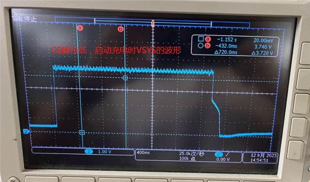
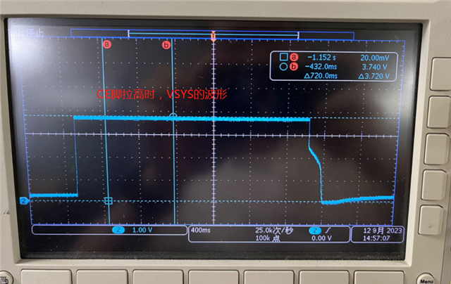
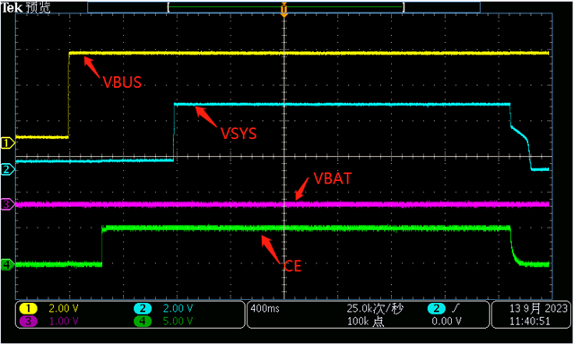
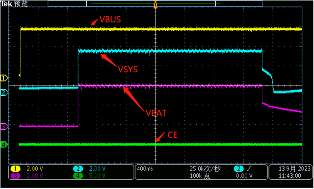
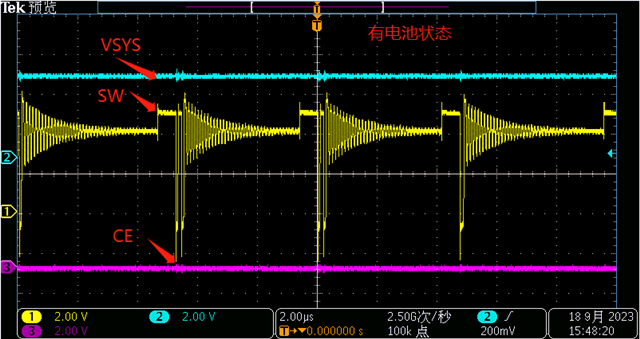
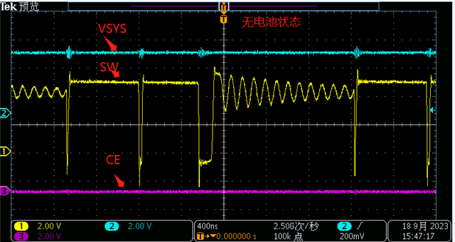
IC of 2021: When the battery terminal is not connected to the battery, VSYS will oscillate and output, and the battery terminal will output 0.7V.
IC of 2022: When the battery terminal is not connected to the battery, after VSYS outputs 3.6V, both VSYS and the battery terminal will stop outputting.
Is this phenomenon due to changes in the power management logic within the IC?
The configuration of Vbq24296_set_sys_min(0x5)in code initialization is 0x5.
void bq24296 set sys min(unsigned int val)
unsigned int ret = 0;
ret = bq24296_config interface((unsigned char) (bq24296 CON1)
(unsigned char)
(val)
(unsigned char)
(CON1 SYS MIN MASK)
(unsigned char)
(CON1 SYS MIN
unsigned int ret = 0;
ret = bq24296_config interface((unsigned char) (bq24296 CON1)
(unsigned char)
(val)
(unsigned char)
(CON1 SYS MIN MASK)
(unsigned char)
(CON1 SYS MIN
Why do chips from different years have different VSYS outputs?
Thanks
Star