This thread has been locked.

If you have a related question, please click the "Ask a related question" button in the top right corner. The newly created question will be automatically linked to this question.

HD3SS3220: No LFPS signal and can't suppprt USB 3.0 SuperSpeed transfer data rate

Part Number: HD3SS3220
Other Parts Discussed in Thread: HD3SS6126,

Hi Team

I've designed the HD3SS3220 USB3.0 port controller to as a USB 3.0 SuperSpeed 2:1 MUX in the PCB board. After power on the PCB board but the SuperSpeed MUX it doesn't work normally. To observe the waveform but there's no LFPS signal can be measured. So the system of HD3SS3220 + HD3SS6126 can't implement to SuperSpeed USB3.0 transfer data rate, it's only support USB2.0 transfer data rate.
Can you help to have some suggestion.

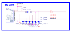
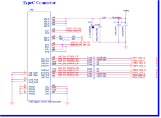
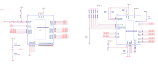
Schematic:
  • Akuan:

          Is the  USBA and USBC connector plug or receptacle? Could be TX/RX signal not connecting correctly.

    Regards

    Brian

  • hi Brian

    Both of the USBA and USBC connector are receptacle

    Could be TX/RX signal not connecting correctly.

    The PCB board has another path from Genesyslogic the HUB IC(GL3590) to HD3SS6126(port SSC0 and SSC1) ,and the USB3.0 is working well. Once switch to HDSS6126R(port SSB0 and SSB1) but USB3.0 do not work. So I think the TX/RX is connecting correctly. I re-check the schematic of the USBC connector to HD3SS3220 and it is correct. Is anything that I was checking incorrect?

  • Akuan:

         SSB0/SSB1 is connected HD3SS3220, which is type-C port. Since you have I2C, can you check

    1: This is UFP application?

    2: if CC communication successfully when connecting to DFP ? 

    3: when you flip USBC cable, DIR status change?

    Best

    Brian

  • Akuan:

         Assume TX1/RX1 channel is selected on USBC port: it ends up with host TX to device TX. You should connect host TX to device RX and host RX to device TX.

    Host TX-->USBC cable-->SSRX1(CN7)--> RX1_DS6_C

    RX1_DS6_C-->RX1(u13)-->RX(u13)-->RX_DS6_C

    RX_DS6_C-->SSB1(u12)--SSA1(u12)-->RX_DS6_A

    RX_DS6_A-->STDA_SSRX(CON2)-->USB2 cable-->Device TX

       Also, host side TX and device side TX should already has  AC cap 75-265nf, you don't need those AC caps close to type-C ports.

    Best

    Brian

  • Hi Brian

    Swap the PCB board of the SSTX1(CN7)--> RX1_DS6_C ,and remove AC cap(C118 and C120) of host TX side, The LFPS can be measurement , but the transfer data rate still keep in USB2.0. If I have missed something?

    modify schematic:

  • Hi Brian

    1: This is UFP application? ==> for CON2 , YES.

     2: if CC communication successfully when connecting to DFP ?  ==> There is no CC communication function.

    3: when you flip USBC cable, DIR status change? ==> Yes, it will change the status.

  • Akuan:

     1: since you can see LFPS signal, it seems USB3 signal path is correct now,

    2: DIR changed status when you flip the cable, so HD3SS3220 CC controller works fine.

    3:  There is insertion loss from 6126 (-1.1db) and 3220 (-1.07db) at 5Gbps and plus PCB trace loss. At 5Gbps speed plus the loss from mux and PCB trace, just wiring the TX/RX signal will hurt the SS signal integrity. 

    Best

    Brian

  • Hi Brian

    3:  There is insertion loss from 6126 (-1.1db) and 3220 (-1.07db) at 5Gbps and plus PCB trace loss. At 5Gbps speed plus the loss from mux and PCB trace, just wiring the TX/RX signal will hurt the SS signal integrity. 

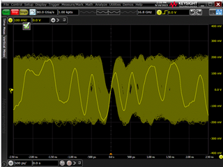
    After measure the waveform of USB3.0, it shows below, and it's quality is really bad. We'll re-layout to correct the circuit of the TX and RX trace swap issue. You've mentioned that wiring the TX/RX signal will hurt the SS signal integrity. Does it is the root cause of the application can't implement to SS data rate? Can you kindly provide the layout suggestion for the modification of PCB board?  Thank you.

    Best regards

    Akuan

  • Akuan:

              Pls check high speed layout guideline below. Wiring is definitely not acceptable for high speed signal over 1Gbps. For this application, since you have two muxes in cascading, you need to get trace length as short as possible

    High-Speed Layout Guidelines for Signal Conditioners and USB Hubs

    Best

    Brian

  • Hi Brian
    We'll follow this guideline for new PCB board.

    Thank you for your help.

    Best regards

    Akuan