Because of the holidays, TI E2E™ design support forum responses will be delayed from Dec. 25 through Jan. 2. Thank you for your patience.

This thread has been locked.

If you have a related question, please click the "Ask a related question" button in the top right corner. The newly created question will be automatically linked to this question.

TPS40007-DIE: Short circuit protection issue

Part Number: TPS40007-DIE

I have some new lots of TPS40007 buck controllers that are displaying a weird behavior. When the unit output is shorted the controller is not entering hiccup mode. Instead a majority of the time the output voltage will dropout and the power will be limited but the voltage is not hiccuping like normal. Sometimes it will it hiccup for a few pulses then dropout into this weird mode. Other times we will get pulses with a larger pulse width. The problem seems worse at cold temperatures. Can you please help me troubleshoot what is happening. Attached are waveforms showing output voltage with wider pulses and with the dropped out voltage. Please know that the short I am applying is less then 10mohms, plenty small enough to push the unit into short. The output voltage is 3.3V the input voltage is 5V, the over current/short circuit setpoint is around 7A-9A

  • Hi,

    Are you using the normal TPS40007 or the DIE version?

    What signals are the 2 waveforms showing?

    Can you add the Vin, SS, SW and inductor current to the scope?

    Chris

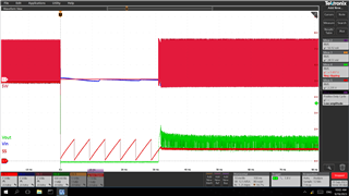
  • Sorry for my delayed response I was out of town last week. We are using the DIE version. the waveforms above show Vout during a short circuit condition. The last pulse in the first waveform shows what we are seeing when the unit is on the borderline of having the issue. We get these wider pulses. If I decrease the temperature a little bit the first waveform will become exactly the same as the second waveform.  Attached are Waveforms you requested from a working unit and a Failed unit. The working unit was also had the problem but i reworked the TPS with an old lot from our R&D stock and the problem goes away. 

    Working

    You can see in the waveforms SS pulls down correctly but when the gate returns the SS pin charges up to 800mV and stays there. The gates then switch at a low duty cycle providing a continues short circuit protection. Please let me know if there is any additional information you need.

  • Thanks for sending the waveforms of a good unit and bad unit.

    Can you add the inductor current to these graphs and provide a zoom in (maybe 100usec/div) of the 7th SS cycle, where it tries to restart?

    It looks like that for the bad unit, the SS voltage is not getting high enough to finish the SS.  Your inductor current waveform will confirm, but it should operate in current limit until SS reaches the ~1.3V threshold and then count 7 pulses of OC.  Then, it would restart.

    "During this soft-start interval (whether or not the controller is attempting to do a fault recovery or starting for the first time), pulse-by-pulse current limiting is in effect, but overcurrent pulses are not counted to declare a fault until the soft-start cycle has been completed. It is possible to have a supply attempt to bring up a short circuit for the duration of the soft start period plus seven switching cycles."

    So, the question is: why does the bad unit never reach 1.3V on the SS pin?  Maybe there is some leakage on the SS pin that is sinking the 3.7uA current source.

    I also noticed that the SS waveform have different slopes between the units.  Are you using a 10nF (or 12nF) SS cap?  You might try swapping the SS caps between the good and bad and/or replacing the bad unit's cap with a fresh one to see if that changes the SS waveform.

    Finally, if you are open to more experiments, you might see if getting the SS pin above 1.3V on the bad unit gets it into the proper hiccup operation.  As a first thought, you should be able to put a 1M resistor from Vin to SS to add to the SS pin's current and drive the pin higher.  You might have a better idea.

    Chris