This thread has been locked.

If you have a related question, please click the "Ask a related question" button in the top right corner. The newly created question will be automatically linked to this question.

TPS25750: Power negotiation

Part Number: TPS25750
Other Parts Discussed in Thread: TIDA-010047, TIDA-01623, BQ25731, BQ25730, BQ25756, TPS25751

Hi,

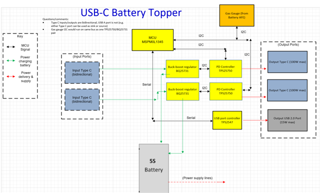
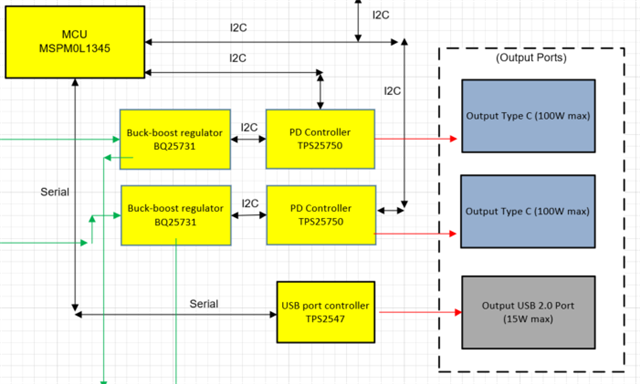
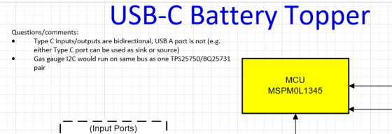
I am trying to find some guidance on power negotiation. The application is a battery topper that would be placed on an existing 5s (18V) battery and ideally, I have 2 USB-C ports that output up to 100W and 1 USB A port that outputs up to 15W. The customer would also like to be able to charge the battery through either USB-C port. I have looked into the TPS25750 and am not sure if I could use two of these to accomplish what I am trying to do with the USB-C ports. I want to know if I am charging the battery with 1 USB-C port while charging a device through the other USB-C port, how I would negotiate the power. Or if I am charging devices through both USB-C ports, can I negotiate independent voltage contracts? I want to charge the battery and the devices as fast/much as possible given the USB-C compliance.

Is there a reference design you can point me to? I have found TIDA-01623 and TIDA-010047 which are 100W applications but not quite what I am looking for.

Thank you,

Randy

  • I forgot to add, I am only interested in power and NOT in data.

  • Is this for an AC/DC design?

  • Hi Randy,

    If I understand correctly, the battery topper goes on top of the battery and has two USBC ports that can either be used to charge the battery or to charge an external device from the battery. 

    Since you would be using two completely independent PD chips, power negotiation would occur separately for the two ports.

    • When you use both ports to charge external devices, you will be negotiating independent voltage contracts.
    • When you charge the battery with one port and have the battery charge an external device with the other port, the power negotiations would also be separate.

    Power negotiations will be based on the source and sink PDOs that you configure in the tx source capabilities and tx sink capabilities register.

    I will look into reference designs for this application and get back to you.

    Best,

    Alex

  • Yes, you understand correctly. There is also a USB-A port I am using to output 15W. It seems that I will need an MCU (M0 or MSP430) to negotiate the power for each of the ports.

  • DC/DC design, the power is directly from an 18V battery pack (think of the battery packs used for indoor power tools like drills).

  • Hi Randy,

    From the power negotiation perspective, the only thing the PD controller will do is advertise source capabilities or sink capabilities that are programmed in the PD's host interface registers, before requesting or accepting a valid PD contract. The PD controller does not do anything to balance power with other PD controllers when sourcing/sinking.

    Typically, for such an application, battery charger ICs are needed to regulate power to/from the battery. These battery charger parts will handle much more of the power exchange between battery and PD controller. I am not an expert in battery charger parts, but TI has a team that works on these. I would expect to need two battery charger ICs, one for each PD controller.

    Can you send me a block diagram of your anticipated design? 

    Best,

    Alex

  • Here is my block diagram. The overview looks blurry, so I zoomed in and included closer screenshots on main components. What else am I missing? I would guess I would also need ESD protection on the input/output ports (both USB C and USB A--3 ports total) and maybe from the battery connection too.

    Note: I drew the input ports separate from the output ports however the TPS25750 are bidirectional and would be the same ports as the output ports shown on the right (there are no separate "input" ports as this functionality is built in).

  • Hi Randy,

    Let me take a look at this and give you some feedback. I think this is generally ok but the power negotiation balancing between the two PD controllers can be difficult to achieve.

    Best,

    Alex

  • Hi Randy,

    One note I have about the block diagram. The way you draw the connection from the input ports to the PD makes it look like the input power into the type C port goes straight to the BQ25731 battery charger. The input power to the type C port will actually go through the PD's internal or external power path first, then to the BQ25731. I just want to make sure there is no misunderstanding here.

    Otherwise, the setup you have looks correct to me from a PD standpoint. Again, from a PD controller standpoint, the TPS25750 only advertises source/sink capabilities, negotiates a PD contract, and then starts sourcing power from the BQ25731 or starts sinking power from the type C port to the BQ25731. The PD will not perform any balancing of power contracts apart from what you configure it to be able to source/sink in the host interface registers.

    I can point you to the BQ battery charger team if you would like. They can give support regarding how the two BQ25731 parts will draw power from or send power to the battery. Please let me know if you would like me to redirect you.

    Best,

    Alex

  • Alex,

    Thank you, I will modify the block diagram accordingly. Yes, it would be helpful to get input from the BQ battery charger team. With the current configuration would you suggestion the internal or external FETs on the Power Path? It seems that I would need power path because I would draw from the battery and charge it at the same time.

  • Hi Randy,

    This depends on which variant of the TPS25750 you are using.

    • If you are using the TPS25750D(DRJKR) variant, the PD controller does not support external power paths. The D variant has two internal power paths. You must use the second power path (PPHV) to sink. PPHV is rated up to 28V.
    • If you are using the TPS25750S(SRSMR) variant, the PD controller has only one internal power path (PP5V) rated for 5V source only. For variant S, you would need to use an external PP_EXT power path to sink (controlled by GATE_VBUS and GATE_VSYS signals).

    I will redirect this E2E thread to the BQ team for input on the battery charger parts.

    Best,

    Alex

  • Hi Alex,

    I don't see any question regarding BQ25731. For power path feature, please use BQ25730. 

    Regards,

    Tiger

  • Hi Tiger, If I am using a PD controller with power path, would I need to use a BQ charger with power path too? For example, I am thinking of pairing the TPS25751 + BQ25756 or the TPS25750 + BQ25731. The PD controllers have a power path option which is needed because the end equipment could have power drawn from the battery and the power sourced/charging the battery at the same time. Is that the correct way of thinking of it? And would power path be needed on both the parts of the TPS + BQ pair or just one of the devices (the PD controller or BQ)? Thank you!

  • Hi Randy,

    I believe both power paths are needed. the PD controller takes care of the input side, as an interface to USB-C or USB-A. The BQ device power path is on the battery side. You can have the flexibility to prioritize either the battery power or adapter power, or both. For the BQ device, the difference is the BATFET, which creates a separate system rail from the battery rail. 

    I hope this helps. 

    Regards,

    Tiger