Other Parts Discussed in Thread: LM5146, , CSD19534Q5A
Hey all. I've recently inherited a project from summer intern for the creation of a power distribution board based on the LM5146. I myself have not worked with switching buck converters before. The board takes in ~44V DC and contains 3 LM5146 ICs to drop that down to 24V, 19V, and 12V for various components.
The Problem
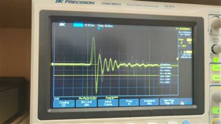
When trying to power a set of 4 motors with the 12V power supply (and this issue has been shown to occur using 1-2 motors as well), we get repeated failure of the output voltage. The image below shows the voltage response measured on an oscilloscope when starting with a single motor load supplied. However, under no load the output voltage correctly goes to 24V.
The result is a clicking sound coming from what I think is the filter inductor a few times per second as it repeatedly energizes and de-energizes. I tried to recreate the existing setup in the TI design tool, and while not all numbers are exactly equal they're pretty close. That result is in the image below.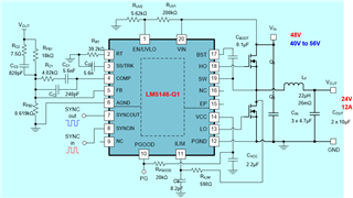
What I've Tried
I looked into this a bit, and found a few resources online including the TI 3-part video series on common buck converter issues. This one seems to me to be the overcurrent protection kicking in. According to the TI design tool excel spreadsheet for the LM5146-Q1, the 590 ohm resistor that they use for R_ILIM would correspond to about 9A current limit but with a test motor connected we're only seeing about 3A inrush current so I wouldn't expect that to be an issue.
Another thing that I saw is that their soft-start time is only about 0.4ms. I thought this might be part of the inrush current problem so I soldered on a 100nF capacitor to increase the soft-start time to about 10ms (which was an interesting experience soldering a THT capacitor to an 0402 component). The oscilloscope result showed that soft-start was working, but we were still getting the same issue. 
Finally, since we were powering these tests with a lab-bench power supply, I set the current limit on the supply to zero, energized the system, and slowly ramped the current limit up. In this case, the motor slowly ramped up speed and eventually reached full no-load speed which drew around 0.6A. If I ramped up the current too fast the system would shut off, but if I went slowly it would work fine. So as far as I can tell, it is the current limit feature, I'm just confused about why it's kicking in at such low currents (generally around 0.7A by our testing).
Another thing that might be useful info is that the inductor used is probably a bit too small for this application. The MSS1210-223ME, which has a 30% saturation current of 8.8A and a rated RMS current of 4.4A. However, while that would struggle with the load of all 4 motors, I wouldn't expect it to be an issue when testing with 1 motor on the 0-3A range.
So, does anyone know what might be the issue here? Since both myself and the intern I inherited this from were new to switching regulators we're hoping that it's something obvious that someone with more experience would be able to recognize.