This thread has been locked.

If you have a related question, please click the "Ask a related question" button in the top right corner. The newly created question will be automatically linked to this question.

BQ79656-Q1: BQ79656

Part Number: BQ79656-Q1

Hi,

I am using TI's BQ79656 BMS IC for cell voltage sensing using a bridge IC BQ79600 between host controller and slave through SPI communication. I am using EVM boards for development. I am able to wake up both the bridge IC and slave IC as per ping and tone mentioned in the data sheet, as I am able to see green led glowing on both the boards. But as soon as I start implementing auto address and voltage polling frame sequence, I don't get any feedback from slave BQ79656, as there is no data transmission from slave when I connect DSO on MISO line.

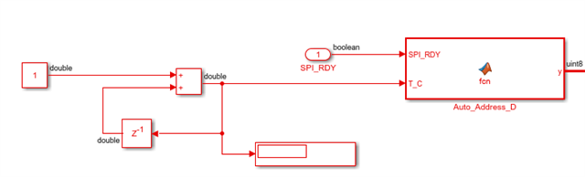
As per data sheet, for write command slave doesn't incur any response frame but for read it should. I am suspecting issue is related to SPI_RDY pin behavior. I am following the SPI_RDY pin check before I even start write/read on MOSI but during power up time only the pin stays high for some time and remains low for most of the time, due to that my program gets stuck for SPI_RDY pin check and holds the data tx on MOSI.

Kindly guide me to solve the problem.

Thanks,

Vamshi

  • Hi Vamshi,

    Could you send a capture of your SPI commands? Are you following the auto address sequence in the datasheet? 


    Thanks,

    Chase

  • Hi Chase,

    I have access to SPI sample code provided by TI mysecure SW. So, I am following the sequence as per that only. Below is the code for your reference and verification. 

    FYI I am only using single slave device for the sensing of 16 cell voltages, there is no any other stack device present in system.

    //AUTO ADDRESS SEQUENCE
    //**********************
    void SpiAutoAddress()
    {
    //DUMMY WRITE TO SNCHRONIZE ALL DAISY CHAIN DEVICES DLL (IF A DEVICE RESET OCCURED PRIOR TO THIS)
    SpiWriteReg(0, OTP_ECC_DATAIN1, 0X00, 1, FRMWRT_STK_W);
    SpiWriteReg(0, OTP_ECC_DATAIN2, 0X00, 1, FRMWRT_STK_W);
    SpiWriteReg(0, OTP_ECC_DATAIN3, 0X00, 1, FRMWRT_STK_W);
    SpiWriteReg(0, OTP_ECC_DATAIN4, 0X00, 1, FRMWRT_STK_W);
    SpiWriteReg(0, OTP_ECC_DATAIN5, 0X00, 1, FRMWRT_STK_W);
    SpiWriteReg(0, OTP_ECC_DATAIN6, 0X00, 1, FRMWRT_STK_W);
    SpiWriteReg(0, OTP_ECC_DATAIN7, 0X00, 1, FRMWRT_STK_W);
    SpiWriteReg(0, OTP_ECC_DATAIN8, 0X00, 1, FRMWRT_STK_W);

    //ENABLE AUTO ADDRESSING MODE
    SpiWriteReg(0, CONTROL1, 0X01, 1, FRMWRT_ALL_W);

    //SET ADDRESSES FOR EVERY BOARD
    for(currentBoard=0; currentBoard<TOTALBOARDS; currentBoard++)
    {
    SpiWriteReg(0, DIR0_ADDR, currentBoard, 1, FRMWRT_ALL_W);
    }

    //BROADCAST WRITE TO SET ALL DEVICES AS STACK DEVICE
    SpiWriteReg(0, COMM_CTRL, 0x02, 1, FRMWRT_ALL_W);

    //SET THE HIGHEST DEVICE IN THE STACK AS BOTH STACK AND TOP OF STACK
    SpiWriteReg(TOTALBOARDS-1, COMM_CTRL, 0x03, 1, FRMWRT_SGL_W);

    Thanks,

    Vamshi

  • HI Vamshi,

    When you see SPI_RDY go high do you drop the CS signal? After dropping the CS signal then you can send the write command. After the write command then pull CS high.

    Then to read, wait for SPI_RDY to go high, drop the CS signal and send the read command and raise the CS. Then you should check SPI_READY to be high again then drop the CS, read your data, and then stop the CLK and and raise CS high. You can see the flow chart in the BQ79600 datasheet on page 20

  • Hi 

    We are using MATLAB function to do the auto addressing sequence. 

    Since it is a model-based approach, the CS signal is automatically pulled down before command is sent and pulled up after the command is sent. 

    We have implemented a counter as shown in the figure - 

    The counter is to move in a sequential fashion.

    The below function is used to proceed for a single device Auto-addressing.

    function y = fcn(SPI_RDY, T_C)
    if(SPI_RDY==1)
    switch T_C
    case 1
    y=[0x90 0x00 0x03 0x43 0x00 0x25 0x2D];
    case 2
    y=[0x90 0x00 0x03 0x09 0x01 0xD3 0x8D];
    case 3
    y=[0x90 0x00 0x03 0x06 0x00 0x17 0xBD];
    case 4
    y=[0x90 0x00 0x03 0x08 0x02 0x92 0x1C];
    case 5
    y=[0x90 0x00 0x03 0x08 0x01 0xD2 0x1D];
    case 6
    y=[0xC0 0x03 0x4C 0x00 0xF8 0xE4 0x00];
    otherwise
    y=[0x00 0x00 0x00 0x00 0x00 0x00 0x00];
    end
    else
    y=[0x00 0x00 0x00 0x00 0x00 0x00 0x00];

    end
    end

    We got this sequence from the datasheet and EVM user guide, but we are unable to get any response from the slave with the above sequence.

    Do we have to monitor SPI_RDY pin during the entire auto-addressing sequence to send individual read/write commands at each consecutive SPI_RDY highs and lows in the above sequence? or is it enough for the SPI_RDY pin to go high one time followed by the 6 steps shown above?

    Also, one other thing we observed is that as soon as we power-up the EVM board it is going to fault mode (indicated by red LED). We are able to wake-up the Slave IC even in this state, but should it go into fault state as soon as we turn it on??

    Thanks,

    Vamshi