This thread has been locked.

If you have a related question, please click the "Ask a related question" button in the top right corner. The newly created question will be automatically linked to this question.

BQ24072: Short Circuit Condition

Part Number: BQ24072

Hello all,

just wanted to clarify my understanding of the BQ24072 and the short circuit circuitry when an input source IS NOT connected. 

My understanding is that if Vout drops more than 250mV below Vbat for a period longer than 250us tDGL(SC2), then OUT should get turned off for a period of 60ms tREC(SC2).

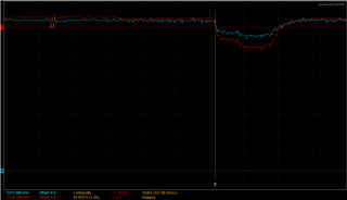
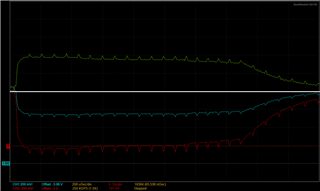
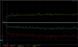
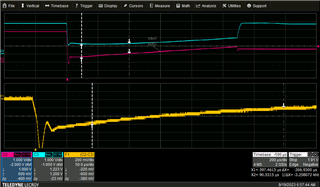
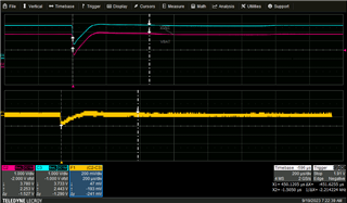
In practice, on startup of my device, I'm seeing my Vout drop below my Vbat by up to 350mV, for longer than 250us, but I don't ever seem to see Vout turn off. I've attached a scope image comparing Vbat (BLUE) and Vout (RED). Am I not understanding the short circuit circuitry correctly? Could my scope be grossly inaccurate...?

  • Hi Lorenzo,

    Are you able to do a math waveform on your oscilloscope? It does look like 250 mV difference occurs at one point but possibly on the borderline of what the Vo(SC2) or tdgl(sc2) threshold is for this particular device. 

    The good news is you understand it perfectly fine!

    Best Regards,

    Anthony Pham

  • Hi Anthony,

    thanks for the reply. I'm attaching a couple more images to the post. Unfortunately I don't have the best scope, but I think it should be sufficient for the measurements I'm taking. 

    The green line is the subtraction of red(OUT) from blue(BAT). The solid white line is the zero point/reference of the subtraction function. The math function utilizes the same scale as CH1, so each vertical line represents 200mV. From what I'm capturing, it seems like the difference between BAT and OUT can even reach 400mV, but OUT does not seem to get turned off. If we were operating at the margins, I'm a little surprised that I've seen consistent startup across my prototypes. Any ideas?

    The first image is with 200us time scale. The second image is with 100us time scale. 

  • Hi Lorenzo, 

    Let me reserve some lab time to take a look at this. My understanding of the short circuit protection is the same as yours at the moment but let me double check.

    I appreciate your patience as we figure this out. 

    Best Regards,

    Anthony Pham

  • Thanks Anthony. I'm curious to see what you will find. 

  • Hi Lorenzo,

    So I was able to go into the lab and was able to take a look at the short circuit behavior. I did something similar where I am adding a capacitor after OUT is turning on. 


    You can see that this is where OUT is not being powered by BAT once it's the inrush disappears.


    For this one you can clearly see that OUT is not detected as a short circuit. 

    From the looks of it, your device definitely did not detect a short circuit condition. Do you see this on multiple devices by chance? What if you were to change the IC?

    Would you also be willing to share the schematic? Just the charger portion would be perfect. 

    Best Regards,

    Anthony Pham

  • Hi Anthony,

    Thanks for taking a look at this.

    in the first plot, which segment is the shortcircuit mode activated?

    During the recovery period, should Vout not be 0V?

  • Hi Lorenzo,

    You can see short circuit activated after the inrush when VBAT rises back up. 

    VOUT voltage will be dependent on your load. In these images, I've no load aside from a capacitor that I was using for the inrush current. If you have a load, this voltage will go to 0 V.

    Best Regards,

    Anthony Pham

  • Hi Anthony,

    I think I understand.

    Just curious then, it seems like it takes longer than the tDGL(SC2) 250us for the short circuit circuitry to activate? Am I understanding this correct? 

  • HI Lorenzo,

    The device recognizes the deglitch within this image prior to the OUT pin not being connected to the battery anymore. 

    Best Regards,

    Anthony Pham

  • I see that, but I'm just trying to make sense of how I'm understanding the datasheet with what I'm seeing in the plot.

    Based on what I can see from the math function, Vout is below Vbat by more than 300mV upon startup. Based on data sheet, if this condition lasts for 250us, the short circuit circuitry should activate then, but in the plot it looks like it only activates after almost 1ms? 

  • Hi Lorenzo,

    Based on your observation, this would be correct. 


    Best Regards,

    Anthony Pham

  • If this is the case, I go back to my original question then, am I understanding the datasheet incorrectly as far as the section "9.3.4.2 Input Source Not Connected" is concerned?

  • Lorenzo,

    Let me take a second look at this in the lab. I realized that the battery may be dropping too far in the tests I ran. 

    Best Regards,

    Anthony Pham

  • Thanks Anthony. I look forward to your findings.

  • Hi Lorenzo,

    Good news! It looks like you are in fact understanding the datasheet correctly. Apologies for the confusion. 

    I've added also the battery current as well so we can really see that at the t_DGL(SC2) time, the battery current goes to 0 and so the path from BAT to OUT is not conducting. 

    Best Regards,

    Anthony Pham