Dear team,
My customer would like to use TPS48111 for their application.
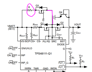
- application : 48V/200A E-Relay with Pre-charge for battery system.
Please review below schematic and let me know your opinion
48V_200A_E-RELAY_230914_R00.pdf
Thank you.
Dear team,
My customer would like to use TPS48111 for their application.
- application : 48V/200A E-Relay with Pre-charge for battery system.
Please review below schematic and let me know your opinion
48V_200A_E-RELAY_230914_R00.pdf
Thank you.