This thread has been locked.

If you have a related question, please click the "Ask a related question" button in the top right corner. The newly created question will be automatically linked to this question.

LM5177: Issue with sync function

Part Number: LM5177

Hello Ti team,

We are now using LM5177 to build a 4 switch converter.

With 50V input / 51.5V output 14A output current using 1mOhm shunt resistor.

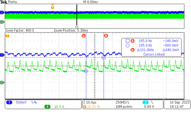
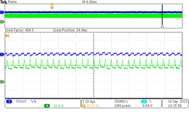
We found different behavior between sync pin being pull-up and sync pin being switched (300kHz PWM)

From inductor current, the upper image shows a glitch every 3 switching cycles (100kHz) which matches the PLL refresh rate when using an external PWM signal.

However, with lower images show no glitch with sync PIN pulled to 3.3Vcc under same test condition.

Please help us figure out what's going on with the internal PLL mechanism.

Thanks.

CH1 is output voltage ripple ,CH2 is inductor current

  • Hi Chris,

    Thank you for using E2E forums, just to confirm are you asking why the waveform looks "glitchy" when you are using external clock? Is it possible to share the Vsync signal? or the input fed to this signal?

    BR,

    Haroon

  • Hi Haroon 

    I have another test condition with 5 LM5177 being interleaved (72deg per phase).

    CH1 is output voltage.

    CH3 and CH4 are the inductor current of phase 2 and phase 1 with CH2 being Vsync of phase 1.

    The inductor current pattern should be the same with internal Vsync considering output voltage ripple.

    Also, the input voltage is provided using 52V battery pack.

  • Hi Haroon

    Here is another screenshot with same test condition.

    The inductor current (CH4) looks jitter while the other(CH3) dosen't.

    After we found the difference between use external Vsync singal and Vsync pin being pull-up to 3.3V.

    We've try to use only one phase and an external waveform generator(with 50% duty cycle and 300 kHz PWM).

    And the test result is that when using external Vsync sginal,the inductor current looks jitter like the earliest post.

    However,when sync pin being pulled to 3.3V this kind of jitter didn't happen.

  • Hi Chris,

    It seems to me that your input signal to Vsync is not very clean and I see these small noises on it, but let me ask some of my seniors and get back to you.

    Thank you

    BR,

    Haroon

  • Hi Haroon,

    As you mention,there is indeed some noise on Vsync signal.

    The Vsync signal from the previous reply is generated by the MCU.

    So there must be some noise because aux power is switching.

    And it seems that the noise doesn't exceed the sync input positive going threshold which is 1.19V on datasheet.

    Furthermore,the Vsync signal from the earliest post is generate by the commercial waveform generator which is from Keysight.

    Hope these information will help you.

    Thank you for helping us

    BR,

    Chris

  • Hi Chris,

    Are all of the 5 LM5177 devices synchronized externally using functional generator and phase shifted by 72 degrees?

    Additionally, I want to ask for the schematics of the design and are you using some kind of noise filter for the sync pin when the signal comes externally and is that filter placed close to the IC or far?

    I would also suggest to reduce the voltage you are feeding to the sync pin via functional generator to see if the noise is reduced, you only need 1.19V, so maybe lower the amplitude of function generator signal you are feeding into SYNC pin. My hunch is that the noise in the sync signal is causing this "glitch" on the inductor current.

    BR,

    Haroon