


Other Parts Discussed in Thread: TPS543320
Hello colleagues,
My customer is evaluating TPS543820/TPS543320 as AOZ device replacement:
I started to work on the EVM and switched ON/OFF a 180uF Polymer ELKO. So far, I used the PCB “as is” with 3.3V default setting. Result is that I need to slow down to a rise time of about 200us, which means ~3A current to not trigger the short circuit detection. I also tried to add a 180uF bulk cap to the EVM PCB, which did not really improve things (I guess due to the reduced control BW by that).
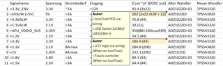
I need to go on working a bit more detailed on the situation, but I think maybe I can share the updated power rails that I want to replace: “Alter Wandler”=Current Solution / “Neuer…”=Redesign
Cout: Total value all over the PCB, in brackets it is the capacitance right at the DCDC outputs in the AOZ designs. The caps right at the DCDC is what I can optimize.
Eingang=Input voltage is 12V on all DCDCs.
For the #2/+5V rail: Current is 3...4A, but to re-use parts, I’ll use TPS543820. There is a load switch from +5VALW to +5V. I will try to change that and use the enable. On this rail, there are load switches on our self-build board and to the USB ports. So, I would see some amount of bulk cap added to the DCDC converter output. But I need to figure out, how to do that best. On the EVM there is C27 introducing zero at ~250kHz and pole at >1MHz, maybe shift that to a lower frequency and change MODE pin?
Any comments or recommendations are welcome. I need to make that robust regarding load switching in the rails 5V/3.3V.
Thank you,
Daria
