This thread has been locked.

If you have a related question, please click the "Ask a related question" button in the top right corner. The newly created question will be automatically linked to this question.

TPS43061: bottom mosfet of boost controller overheats

Part Number: TPS43061

Hi,

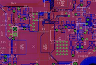
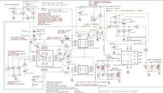
We have a design based on tps43061/43060, the current pcb has a tps43061.
The boost controller is used to boost a 12V leadacid battery voltage (can be as low as 9V) to approx 24.4V
which will pass to a module that powers four 24VDC shade motors that each draw
approx 1.7-2Amax.

The motors are supposed to operate in a burst of 40-60secs (full travel takes that time) but the problem is
that the bottom mosfet (Q16) burns out (thermal overheat).
These mosfets (AO4576)are 20A capable so the 8A from the motors should not be an issue
but maybe the inductance of these motors is.
Question: any obvious mistake in the schematic? Or the choice of mosfet is wrong?
What can we do to prevent the heat up of the bottom mosfet?
The top mosfet seems not to heat up, but it has a gate resistor of 0R. The bottom mosfet uses 4.7ohm
as suggested in the datasheet.

  • Hi Peter,

    Thank you for using E2E forums, could you please fill out this excel sheet https://www.ti.com/tool/download/SLVC471 so that I can review your schematic and layout?

    Thank you

    BR,

    Haroon

  • TPS4306x_BOOST_CALCTOOL_REVB.xls

    TPS43061-calculation.txt
    tps43061 calculations
    
    (11)
    Dmax = (Vout - Vinmin)/Vout = (24.55-10)/24.55 = 14.55/24.55 = 0.593
    Dmin = (Vout - Vinmax)/Vout = (24.55 - 14.4)/24.55 = 10.15/24.55 = 0.413
    
    (12)
    Fswontime = Dmin/Tonmin = 0.413/100ns = 4.13MHz
    
    (13)
    Fswofftime = (1-Dmax)/Toffmin = 0.407/250ns = 1.63Mhz
    
    Select Fsw = 750KhZ = 0.75MHz
    
    
    (15)
    Iin = Iout/(1-Dmax) = 8A/0.407 = 19.66A
    
    (16)
    L(uH) >= Vout/(In*Kind*4*Fsw) = 24.55V/(19.66A*0.4*4*0.75MHz) = 1.04uH
    
    Select 1uH (SRP1265A 2.3mOhm 30A)
    
    (18)
    ILrms = SQRT((Iout/(1-Dmax))^2 + ((Vinmin*Dmax)/(SQRT(12)*L*Fsw))^2) = SQRT(386.36+5.21) = 19.8A
    
    (19)
    ILpeak = Iout/(1-Dmax) + (Vinmin*Dmax)/(2*L*Fsw) = 19.66 + (10*0.593)/(2*1uH*0.75MHz) = 21.64A
    
    (21)
    Rcs = Vcsmaxtyp/(1.2*ILpeak) = 68mV/(1.2*21.64) = 2.62mOhm
    Select Rcs = 5mOhm/1W parallel to 5mOhm/1W = 2.5mOhm/2W
    
    (22)
    PRcs = (68mV*68mV)/2.5mOhm = 1.85W
    
    (24)
    Cout > (Dmax*Iout)/(Fsw*Voutripple) = (0.593*8A)/(0.75MHz*0.25V) = 25uF
    Select 27.6uF (10u + 4*(2*2*2u) on module, note: the 4 outputs on module have also 100uF electrolytic)
    
    (25)
    Igd = (Qghs+Qgls)*Fsw = (6.8nC+6.8nC)*0.75MHz = 0.0102A = 10.2mA
    
    The target efficiency of the design dictates the acceptable power loss in the MOSFETs. The two largest
    components of power loss in the low-side FET are switching and conduction losses. Both losses are highest at
    the minimum input voltage when low-side FET current is maximum.
    
    For our purpose:
    NOTE: Therefore when Vbat < 10V we should not allow motor drive but only battery charging until Vbat > 12V again.
    Normally we keep charging the battery but if motors are used intensely the Vbat may become too low.
    
    (26)
    Pcondls = Dmax*ILrms^2*Rdsonls = 0.593*19.8^2*0.0077 = 1.79W
    
    (27)
    Psw = (Fsw/2)*(Coss*Vout^2 + ((Vout*Iout)/(1-Dmax))*((Qgd*Rg)/(VCC-Vgs))) = (0.375Mhz)*(440p*24.55^2 + ((24.55*8A)/(1-0.593))*(3.6n*1.5)/(5.5-1.8))
    = (0.375MHz)*(0.265u + 482.56*1.46n) = 0.375MHz*0.97u = 0.36W
    
    (28)
    Pcondhs = (1-Dmax)*ILrms^2*Rdsonhs = 0.407*19.8^2*0.0077 = 1.23W
    
    (29)
    Pdt = Vsd*ILrms*(Tnonoverlap1 + Tnonoverlap2)*Fsw = 0.7*19.8A*(65ns+65ns)*0.75MHz = 1.35W
    
    
    Voltage divider: Rhs=10k, Rls=0.523k
    
    (43)
    Rcomp = (40/3)*(2*3.14*Cout*Rsense*Vout*Fco*(Rsh+Rsl))/(Rsl*Vinmin*Gea) =
    = (40/3)*(2*3.14*27.6u*2.5mOhm*24.55V*Fco*(10k+0.523k)/(0.523k*10V*1100) = 10000 (we selected Rcomp=10k)
    Fco = 10000/259.44 = 38.5kHz
    
    (44)
    Ccomp = 1/(2*3.14*(Fco/10)*Rcomp) = 1/(2*3.14*3.85k*10k) = 4.1nF
    We selected 100nF
    
    (46)
    Chf = 1/(20*3.14*Fco*Rcomp) = 1/(20*3.14*38.5k*10k) = 41.3pF
    Select 100pF


    I filled in your excel sheet and added a text file with my calculations.

    I noticed the Chf (calculation 46) on our board was mistakenly set to 0.1u instead of 0.1n
    so I assume we better remove Chf or put on the 100p that it should have been.

  • Hi Peter,

    Yes could you let me know how your board works with that CHF changed? does it solve your issue?

    from the spreadsheet your loop compensation does not look very good I would fix that, you need higher PM and also GM should be at least -10dB.

    I would change Rcomp to 5k ohms, Ccomp to 15nF and CHF can stay as it is.

    BR,

    Haroon