This thread has been locked.

If you have a related question, please click the "Ask a related question" button in the top right corner. The newly created question will be automatically linked to this question.

LP8860-Q1: About startup behavior

Part Number: LP8860-Q1

Hello,

I would like to ask you a question about LP8860-Q1.
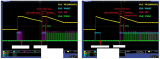
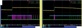
The figure below shows the waveform at startup.
Depending on the device, some devices maintain a constant output voltage during the 50ms BOOST START period, while others reduce the output voltage.
Adaptive mode is set, but which waveform is correct?
Or are both correct behaviors?

Best regards,

  • Hi Colt,

    Our expert is on a business trip, the reply may delay.

    Thanks for your understanding!

  • Hi, Kaji

    pls help to read the maximum value for the startup. I supposed that they are different.

  • Thank you for your reply.
    However, your answer is unclear.
    What I want to know is what happens when the output voltage (VBOOST) reaches the set value within the BOOST START period.
    Should you maintain the set value or stop switching?
    Best regards,

  • Hi, Kaji

    For picture 1, device reaches the target value and keep switching to keep this value.

    For picture, I supposed that the voltage is higher than target value, and voltage drops and FET doesn't switching.

    Does this two waveform catches in one board?

  • Thank you for your reply.
    The two images are of different boards.
    The behavior varies depending on the board.
    Regarding the waveform on the left, I agree that once the set value is reached, switching continues to maintain that voltage.
    However, I do not agree that the waveform on the right exceeds the set value, so switching is stopped.
    If that's the case, shouldn't switching start again once it drops to the set value?
    I'm asking for your opinion because I'm not sure what the correct behavior is.
    Best regards,

  • I will contact you with additional information.
    Attached is an enlarged waveform.
    The waveform on the right seems to indicate that Vboost has exceeded the Boost Overvoltage Protection threshold and stopped switching.
    BOOST_INITIAL_VOLTAGE is 23V and exceeds the +1.6V value.
    Even if the set value is exceeded and the Boost Overvoltage Protection threshold is exceeded, switching should not stop due to the boost start period, right?
    The waveform on the left also exceeds the value of 23V + 1.6V, but switching has not stopped.
    Also, in the waveform on the left, PWM is input during the boost start period, but switching continues even when PWM is off.
    Best regards,

  • Hi, Kaji

    From my side, both two waveform is correct behavior.

    Depending on the different PCB design, the leakage current, the setup and the loop gain is different. It lead to a different ripple of the startup.

    If it is not clear to you, I could support a meeting to explain this in details.