This thread has been locked.

If you have a related question, please click the "Ask a related question" button in the top right corner. The newly created question will be automatically linked to this question.

BQ24171: Schematic review

Part Number: BQ24171
Other Parts Discussed in Thread: BQ27426, , BQ27Z561, BQ27Z561-R2, BQSTUDIO

Hi, 

We are using BQ24171 charger and BQ27426 battery gauge in our board. It will be connected to a 2P 3.7V battery. 

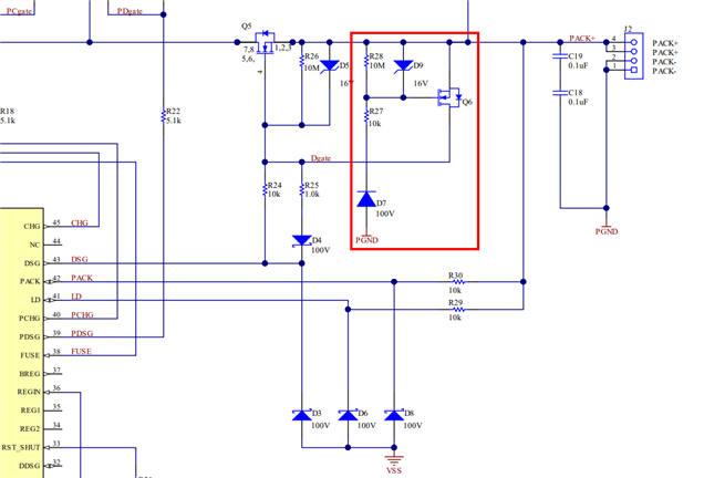
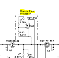
I have attached our schematic for your reference. Please review it and give us your feedback.

5164.BMS.pdf

  • Hi Akilarasan,

    I don't see any obvious errors on the charger schematic.  I have moved this thread to gauge team for their review.

    Regards,

    Jeff

  • Hello Akilarasan, 

    Looking at the schematic for the battery gauge, I don't see any obvious errors here. 

    Regards, 

    Jonny. 

  • Hi Jeff,

    As you can see in schematic, we are not using Temperature sense function. TS pin is applied to 1.414 V. These condition won't cause any error, right?

    Also can you please explain that Reverse Input Polarity Protection, I referred it from eval board schematic.

  • Hi Johnny,

     This BQ24171 charger and BQ27426 battery gauge combination will be okay to use or it will  cause any problem.

    Also I want reverse battery insertion protection. Is there any way i can implement that?

  • Hello Akilarasan, 

    I don't see any obvious issues with the battery charger and gauge combination you have selected, though Jeff can confirm this. 

    This gauge does not have any reverse battery insertion protections. For this protection I would recommend posting a new E2E thread for the battery monitor products team (BMP). They can help identifying secondary protectors with reverse battery insertion protection. 

    Regards, 

    Jonny. 

  • Hi Jeff,

    As you can see in schematic, we are not using Temperature sense function. TS pin is applied to 1.414 V. These condition won't cause any error, right?

    Also can you please explain that Reverse Input Polarity Protection, I referred it from eval board schematic.

  • Hello Akilarasan,

    To clarify, do you want a reverse-charger circuit or a reverse-battery circuit?

    We have previously only implemented reverse-charger protection circuits. A common configuration would be something like shown here:

    PACK+/PACK- is where the charger would be attached to charge the battery. If attached backwards, the Q6 FET turns ON to clamp the voltage on the Q5 FET.  As to how this circuit would work, we have an explanation in Section 2 Reverse Charge Circuit and Section 3 Reverse Charge Component Selection of the Multiple FETs with the BQ76952, BQ76942 Battery Monitors application note. This is for a different device family, but the concepts of the reverse-charger circuit apply the same.

    I notice you have a similar circuit to this on your schematic. I would recommend to add a diode like the one I showed above to ensure the leakage current to ground is minimal. Also, with this circuit, there may be current flowing from ACDRV to whatever is connected to the drain of Q6 or Q7. 

    Q9 would short the gate-source of the FETs, so now the ACDRV voltage can flow through the body-diodes of the N-Channel FETs.

    I am not sure if this much a concern. Jeff may be able to comment on that.

    Best Regards,

    Luis Hernandez Salomon

  • Hi Luis,

    Thank you for the reply. Could you also please explain me  about this following protection circuit, it is from BQ24171EVM-706-15V evm board schematic.

  • Hi Akilarasan,

    Q1 turns on and its body diode clamps the input voltage seen by the charger to no lower than 0.6V below ground.

    Regards,

    Jeff

  • Hi Jeff,

    Thank you for the replay.

    Hi Luis, I have a small doubt regarding battery gauge. We will be using INR18650 M36T 12.50Wh which has following spec.

    Will  BQ27426  battery gauge work for this battery? 

    Nominal energy 12.50Wh
    Minimum energy 12.10Wh
    Nominal voltage 3.63V
    Standard charge current 1000mA (0.3C)
    Charge end voltage 4.2V
    Charge cut-off current 50mA
    Max. charge current 1000mA (0.3C) at 0-24C, 2330mA (0.7C) at 24-50C
    Max. discharge current 5000mA

  • Hello Akilarasan, 

    Looking at the battery specs you have provided, the BQ27426 gauge should work with your battery.

    Another option would be to use the BQ27Z561 gauge. The difference here is that the BQ27426 is a ROM gauge and the BQ27Z561 is a flash gauge. By using a flash gauge you will be able to program the gauge with a chemistry that is similar, if not the same as your battery. Another difference is the implementation of the gauge, as the BQ27426 is a system side gauge and the BQ27Z561 is a pack side gauge. 

    Regards, 

    Jonny. 

  • Hi Johny,

    I want to add one battery protector IC with this existing schematic. Please recommend one which will be suitable with this gauge IC and charger IC. 

    Also, we don't have lot of space in board. So, please recommend which will be smaller and compact

  • Hello Akilarasan, 

    I will assign this thread to the monitors team experts.

    Regards, 

    Jonny.

  • Hi Johny,

    As you have suggested, I have changed gauge IC from BQ27426 to BQ27Z561YPHR-R2 in our schematic. I have attached schematic for you reference. Please check once and give your feedback.

    Battery Charger and Battery Gauge.pdf

    Also I have some doubts regarding BQ27Z561YPHR-R2 design:

    1. I have used high-side configuration. Is there any advantage in low-side compared to high-side configuration.

    2.why 49.9 ohm resistor is required between SRP/SRN and battery?


    Also some doubts regarding BQ27Z561YPHR-R2 functionality:

    1. What is pulse signal used for?

    2. Can I use interrupt signal as batt low warning signal?

    3.I2C address is not available in datasheet.

    4.I'm already using one thermistor for charger. Do I need to add one for gauge IC or I can leave the pin floating?


  • Hello Akilarasan,

    In the future I would recommend to open different threads for different devices, so it becomes easier for us to track the thread and answer more efficiently (we are multiple groups). Asking new questions, specially if it is about very different devices, makes support more difficult for us.

    Regarding which protector would be suitable, the BQ298x family probably would fit your requirements. You will have to check if there are any already released devices that meet your system/battery requirements.

    I will let gauges team answer the question about the BQ27Z561 device.

    For any further protector questions, please create a new thread.

    Best Regards,

    Luis Hernandez Salomon

  • Hello Akilarasan,

    The TRM contains the details about the PULS pin operation: 7.1 Description

    You can review the TRM for information regarding the interrupts the BQ27Z561 can provide, there are multiple different configurations available.

    The device address is in the TRM, section 10.2 I 2C Interface for the -R2 firmware.

    The BQ27Z561 should be the only device with a thermistor, the optimal configuration is the gauge uses the thermistor data to report ChargingVoltage() and ChargingCurrent() to the host which then controls the charger, so everything is configured in the gauges Advanced Charge Algorithm.

    BQ27Z561-R2 TRM: https://www.ti.com/lit/ug/sluuc54b/sluuc54b.pdf?ts=1697493962067&ref_url=https%253A%252F%252Fwww.ti.com%252Fproduct%252FBQ27Z561-R2

    Sincerely,

    Wyatt Keller

  • Hi Luis,

    Regarding schematic review, any feedback is there from your side?

  • Hi Wyatt,

    In our design, we didn't use smart charger where FPGA /processor will control the charging voltage or charging current. In that cause we can get the temperature information from the gauge IC, but we can't do nothing about it. 

    I'll be using two thermistor - one for charger to control charging under appropriate temperature and one for gauge IC  to check whether discharging is happening at higher temperature. 

    Also, tell me this. Without BQstudio, I can able to configure gauge IC and perform my functionality, right?

  • Hello Akilarasan, 

    No, to configure the gauge you will need BQStudio to upload the ChemID onto the gauge since it contains proprietary information. 

    Regards, 

    Jonny.