- Ask a related questionWhat is a related question?A related question is a question created from another question. When the related question is created, it will be automatically linked to the original question.
This thread has been locked.
If you have a related question, please click the "Ask a related question" button in the top right corner. The newly created question will be automatically linked to this question.
Hi,
we are facing same problems discussed in the following thread about gate ringing oscillations:
Unfortunately in that thread no solution was post.
We are using UCC21521 gate drivers and SiHA100N60E as mosfets for a BLDC motor application with 390V bus.
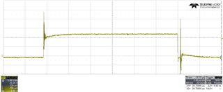
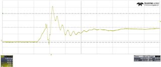
Actually we are verifying mosfet Vgs and Vds without any load and just one branch. High-side mosfet shows oscillations in the plateau region with spike near 25V. Low side mosfet Vgs is very clean
Gate resistors are actually: 10R for turm-on path and 10R//10R for turn-off path. We also added a gate RC-snubber (5R, 10nF) that seems to reduce ringing amplitude on high-side Vgs.
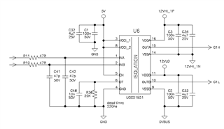
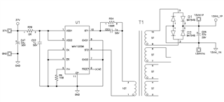
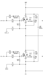
Here the high-side Vgs waveform:
Thanks
Hi Nicola,
You share the first name of a legendary motor designer!
This sounds like a problem related to high switch node ringing. As the switch node is shorted to the HV bus when the high-side is closed, there is probably room for improvement on your HV power supply decoupling. This high ringing needs to be addressed at the high power level; snubbers on the gate will at best slow the switching down and increase switching loss.
One possible solution is to use a high voltage electrolytic capacitor. It will naturally act like a snubber on the HV rail. However, they are anethema to many motor designers due to long term reliability concerns. Also, the large component can dissipate several watts of instantaneous power without damage.
The next option is to design a high power HV bus snubber. You will need to use several high power, low resistance resistors in parallel to absorb the power without damage. Often I have seen customers add many many many parallel capacitors on their HV bus to decouple the HV supply sufficiently. Resistance in series with these capacitance will help dampen the oscillation of whatever inductance still remains in the power loop, and any voltage sag they create will just help reduce Miller charge injection.
Once you start to tame the switch node + bus oscillation, I believe that the gate driver noise will also be eliminated, and you can focus on optimizing the switching losses by increasing drive strength! It will be a balance between how much power you need to snub due to fast switching and how much power you will burn in switching loss if you switch more slowly.
Best regards,
Sean
Thanks for the reply and for the suggestions. We will try these solutions. Anyway, does TI have any application note about HV motor inverter application?
Thanks
Hi Nicola,
I learned everything I know from the DRV8301-69M-KIT. It is a good start, but most of the learning was the hard way. There are too many things that can go wrong to list here! But I did write this app note to help you with the current sense amplifier circuit: https://www.ti.com/lit/ug/tidueh2c/tidueh2c.pdf
Best regards,
Sean