This thread has been locked.

If you have a related question, please click the "Ask a related question" button in the top right corner. The newly created question will be automatically linked to this question.

TPS40210: Power up issue in different adaptor input

Part Number: TPS40210

Hi Sir,

 My customer us TPS40210 for 5V to 48V application. They change switching frequency from 600KHz to 300KHz for reducing heat issue. (It's 600Khz version. They change R6/R13 to 500Kohm, adjust C15, but didn't change inductor)

We have some condition currently:

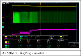
1. 600KHz switching: Output is fine but MOSFET is hot.
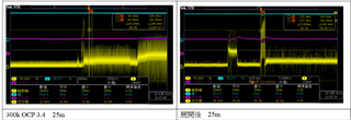
2. 300KHz with adaptor A, Output is fine.
3. 300KHz with adaptor  A+ (OC limit increase to 7A), Output is failed.
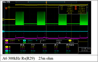
4.300KHz with adaptor A+, change R29 from 25m to12m ohm.
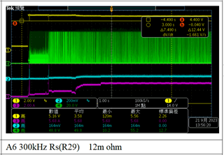
 We think changing larger L might improve Inductor current and prevent OC protection. But we can't explain why we can't see abnormal Vsense (maybe it's filtered?). Would you please helping to review the circuit / waveform and provide suggestion how customer have to modify their design. Thanks for your kindly help.

Best regards,

Gary Teng


  • Hi
    My name is Ron and I am the hardware enginner from ATEN.
    I have some question:

    1.According to my test in my board,My operation frequency is 600kHz and 300kHz,I measure ISNS voltage that is under 150mV,but TPS40210 will enter to protection mode.And when I measure ISNS voltage that is over 150mV,The TPS40210 will not enter to protection mode.What is mechanism determine enter to protection mode?
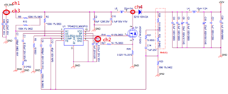
    2.Could you help me check my circuit is right?(note:Correct C15 is 330pF.)
    3.Could you provide Maximum and minimum of ISNS voltage,please?

    It's urgent issue,please reply me as soon as possible.
    Thanks for your help.


  • Hi Gary, thanks for reaching out.

    Can you please clarify what are the adaptors A and A+?

    When changing R29 to 12m it works, right?

    It is possible that for the lower frequency the inductor value is too low. Also the RC filter at the current sense pin seems to be much to big. You can try to reduce the filter capacitor (Cx5?)

    Best regards,

    Moritz

  • Hi Moritz,

     Adaptor increase OC ranget in A+ version.

    1. Customer set 20MHz filter at their measurement Do you think that is the reason why we can't make sure about OC and Vsense (OC condition is happened at 120mV~180mV)

    2. RC filter's capacitor is 330pF currently.

    Thanks and regards,

    Gary

  • Hi Ron,

    The mechanism is, that if the voltage at Rsense exceeds the threshold (typical 150mV, min. 120mV max. 180mV), the MOSFET will be turned off. So it will enter overcurrent protection between 120 and 180 mV.

    So with 300kHz and Rsense=12m your circuit works, right? Can you please measure the output voltage as well?

    Please try to increase the softstart resistor R1 to a value between 10-100k. And also please further decrease C15 to 100p.

    Best regards,

    Moritz

  • Hi Moritz,

      About OC voltage range is 120 to 180mV, Can we know how long the voltage will trigger OC condition?

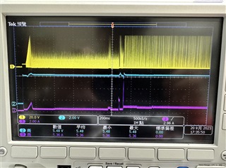
     We're testing customer board with 25m RSENSE. But we see there's over 180mV voltage shown for around 5ms but Vout is still fine. Is the time defined in Tblnk parameter? Or TPS40210 need more time to enter OC?

     And, after we modify RSENSE to 12m ohm, customer's board is fine currently (VSENSE is around 160~170mV). But they want to know why high voltage over 180mV didn't stop TPS40210's output. 

    Thanks and regards,

    Gary

  • Hi Gary,

    After hitting the current limit, the time between the restart attempts is set with the softstart capacitor. The formulas for this are in the datasheet on page 14. With Css=330pF, this time will be around 6us.

    The device has a minimum on-time of 200ns. So if the current exceeds the threshold in the first 200 ns of a cycle, the device is not able to turn the MOSFET off. That might be the reason for exceeding 180mV.

    The ouput will not be stopped in an overcurrent event. Switching only stops for a shor time (selected with Css). In this time the output is supplied by the output capacitors.

    Best regards,

    Moritz

  • Hi Moritz,

     So about the circuit. changing Rsns to 12m ohm is fine for preventing OC condition. What else cusotmer have to take care about the design? 

     Thanks for your kindly help.

    Regards,

    Gary

  • Hello Gary,

    I would recommend checking the design with the quickstart calculator:  SLURB11 Calculation tool | TI.com

    With the reduced switching frequency, the ripple current on the inductor increases, so if there was not a lot margin before, the sense resistor value needs to be reduced.

    The output voltage ripple will increase as the output capacitor is the same.

    There is one other thing that you might check for the thermal issue: Which diode is used? If it is a Schottky diode? Schottky diodes are capacitors and whenever they are turned off, they inject a current spike into the switch.

    Best regards,
    Brigitte