Other Parts Discussed in Thread: BQ40Z50
Hi e2e community,
I am developing a custom board with 3x BQ25798 in parallel. From MSP430, I set low level to CE pin and EN_CHG = 1.
In addition, a custom board with an onboard BQ40z50 is connected to the board.
I can charge the battery pack (1p4s, pack voltage is around 14V ) if a power supply is connected to BQ40z50 board, however if I connect the battery pack to the board (to CN34), the charging status is showing that bq25798 is in termination mode.
From a host MCU, I got the following results:
- REG1B_Charger_Status_0 = 0x2F
- REG1B_Charger_Status_1 = 0xEA
- REG1B_Charger_Status_2 = 0x01
- REG1B_Charger_Status_3 = 0x40
- REG1B_Charger_Status_4 = 0x02
- REG1B_Fault_Status_0 = 0x00
- REG1B_Fault_Status_1 = 0x00
The following pictures are the Bq25798 schematic: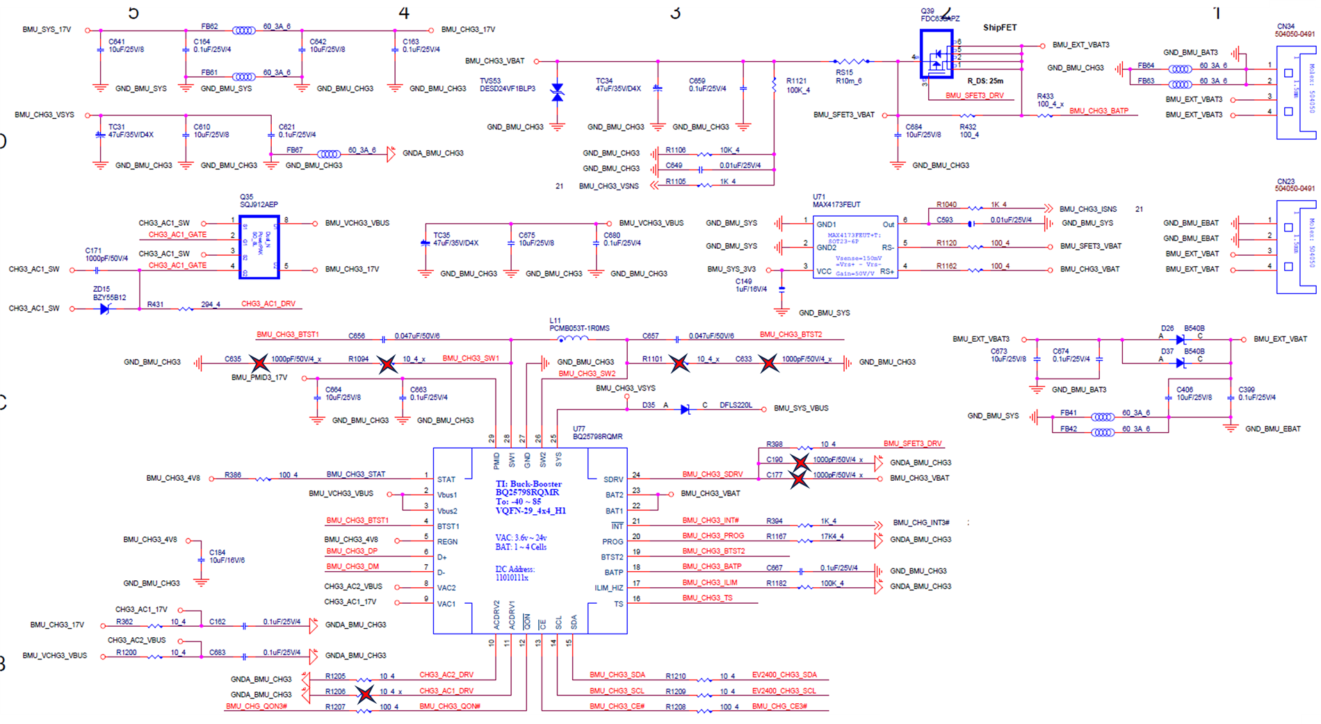
The other two bq25798 ICs have the same circuit (vbus is connected to the same power input and vbat is connected to the same output). The red x symbol denotes that these parts were removed from the board.
I am wondering if these three bq25798 are affecting each other. Does anyone have any idea?
If this design is not valid I will try to disconnect the other two bq25798 from the circuit and charge with only one bq25798.
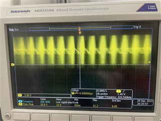
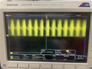
In addition here is the signal measured from SW1 and SW2