Other Parts Discussed in Thread: TIDA-01513, TIDA-010232
Could you please share the details for the Simulation (spice model )for this TPSI2140-Q1. So it will helps us to simulate with all the extreme conditions.
This thread has been locked.
If you have a related question, please click the "Ask a related question" button in the top right corner. The newly created question will be automatically linked to this question.
Could you please share the details for the Simulation (spice model )for this TPSI2140-Q1. So it will helps us to simulate with all the extreme conditions.
Hello Vijaykumar,
Thanks for joining E2E and reaching out to our team! Unfortunately, no PSpice model is available for the TPSI2140-Q1 at this time. However, we are looking into developing one in the near future. What were you intending to simulate so that I can think of a temporary workaround? HIPOT?
Best regards,
Tilden Chen
Solid State Relays | Applications Engineer
Hello Tilden Chen,
Thanks for the response.
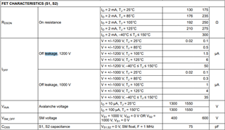
I am looking to simulate the circuit and find out the leakage current error for high and low temperatures. consider 1000V battery pack, with Battery V model reference design, what will be the leakage current and also resistance error. is there any calculation available from the reference design to find out leakage current? In TID01513, isolation leakage current has been measured from EVM, But how do we calculate with extreme conditions?
Regards,
Vijay
Hello Vijaykumar,
Thanks for the update here. For FET leakages, we do spec that across temperature for the TPSI2140-Q1.

I'm not aware of any error calculation tools for TIDA-01513. Have you considered another insulation monitoring reference design, TIDA-010232, for your application? This design is better supported, and my understanding is that we have an error calculator developed internally that we may be able to share.
Best regards,
Tilden Chen
Solid State Relays | Applications Engineer
Hello Tiden,
Thank you.
Yes Its TIDA-010232, reference design which i had referred for error calculation. As you said, if you have developed already an error calculator for this, it would be nice for us to check extreme conditions and also observe characteristics. So hoping to get for some of the reference calculations for the error calculations.
Hello Vijaykumar,
Thanks for providing an update. Let me loop in the correct expert to support you here.
Best regards,
Tilden Chen
Solid State Relays | Applications Engineer
Hello Vijaykumar,
We did some worst case calculations for TIDA-010232, where we assumed the worst case for the most impactful sources of error and did all the possible combinations. We are working on releasing this tool soon.
What I can share for now is, that the behavior we see is similar to the measurements shown in the Design Guide, but since the we assumed all the worst cases, the worst case error is about 5% higher than in our measurements.
The general behavior is the same. For values of RisoP and RisoN much lower than the critical values(<10kOhms), the error gets bigger. The same is true for values above the critical values of RisoN and RisoP(>1MOhm). In the critical range we see worst case errors around 5%.
We looked at the following sources of error:
Offset and gain error of isolated amplifier, Offset and gain error of differential to single-ended conversion, inaccuracy of resistors (assuming 0.1% resistors), inaccuracy of DC voltage 0.5 %, quantization error or 12 Bit ADC.
Best regards,
Andreas