Hi,
I found there is a weird SW waveform resulting in a bad output ripple. I wonder if it's normal and how it happens.
SW waveform
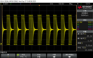
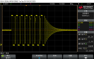
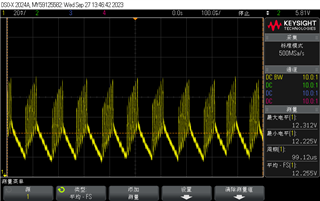
Output waveform
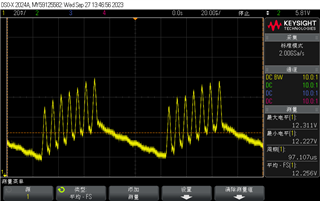
test condition:
VIN = 24V, VOUT = 12V, fSW = 500kHz,100-mA Load, Auto Mode
This thread has been locked.
If you have a related question, please click the "Ask a related question" button in the top right corner. The newly created question will be automatically linked to this question.
Hi,
I found there is a weird SW waveform resulting in a bad output ripple. I wonder if it's normal and how it happens.
SW waveform


Output waveform

test condition:
VIN = 24V, VOUT = 12V, fSW = 500kHz,100-mA Load, Auto Mode
Hi Zehui,
Obviously, the converter are working unstable condition.
Could you share the schematic and layout for further check?
By the way, can you increase the load current to see SW and Vout in CCM condition?
B R
Colin
Hi Colin,
Sorry for late reply. Just come back from long national day holiday.
Here are the SW and Vout at heavy load. Duty cycle is changing, which is confusing.
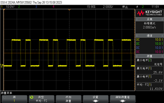
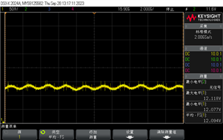
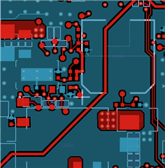
You could check the schematic and layout.
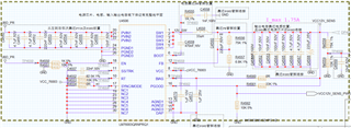
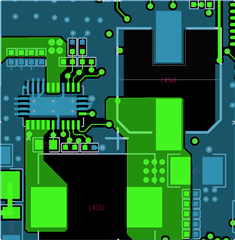
Hi Zehui,
Pls remove Cff(C4560) and test again.
If it is still unstable, pls change Cout(C4566=4.7uF,C4577=4.7uF) to (C4566=22uF,C4577=22uF).
Thanks
Colin
Hi Colin,
It became normal at light load after I removed the Cff.Could you explain why it works?
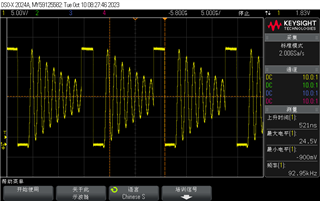
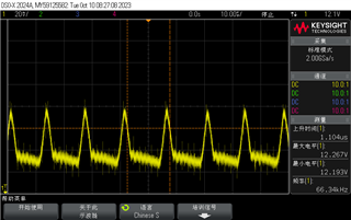
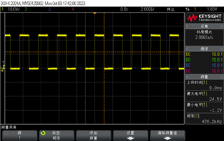
I tried to let it work at FPWM mode with Cff. The Vsw seemed quite normal. Why it's different in two modes.
And without Cff, the performance of load transient is bad. VIN = 24V, VOUT = 12V, fSW = 500kHz, 350 mA to 3.5 A to 350 mA
Load, Auto Mode
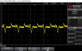
Vout
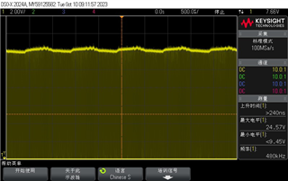
Vsw
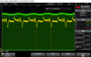
Vout & Vsw
Hi Zehui,
Cff will couple noise into fb pin which can cause unstable issue.
Pls remove CFF and increase Cout to 2x47uF to see load transient performance.
Thanks
Colin