This thread has been locked.

If you have a related question, please click the "Ask a related question" button in the top right corner. The newly created question will be automatically linked to this question.

HD3SS3220: Unknown low frequency pulse and no pull-down resistor on CC ports

Part Number: HD3SS3220
Other Parts Discussed in Thread: 3220UFP-DGLEVM

Hi Experts,

I design my circuit board for USB Type-C interface with HD3SS3220, and checked the waveforms and functions. And I found some strange behaviors on CC1, CC2 ports.

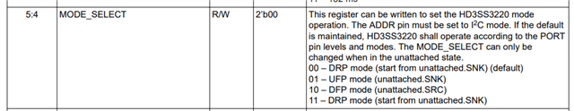
I design my board as UFP and set the ports as below, (I attach a part of schematic)

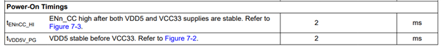
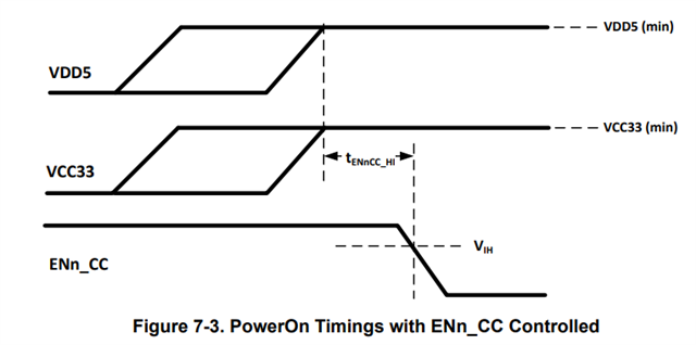
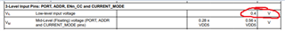
PORT: GND, ENn_CC: GND

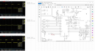
Now I do not connect any USB cable, i.e. CC1 and CC2 are opened exclude ESD passive device on them. I think each of CC1 and CC2 have internal pull-down resisters, around 5kohm for detecting Type-C rotation, however I observed 4.5V pulse with 80ms period. I show it as (1) in attached jpg file. It looks that there is no pull-down resistor. I tried to add 4.7kohm externally between CC1 and GND, then pulse level down to 344mV. Those are showed as (2) and (3). So I think there are no internal pull-down resistors. And this 80ms period noise appears on VBUS in some condition, of course with no USB connection. I guess it is caused by any noise conduction.

Is there any mistake of my design, or  is this behavior natural?

Best regards,

Terry,


  • Hi Terry,

    The CC pins should remain low if they are configured as UFP correctly and no USB is plugged in. It seems that the port may be configured as a DRP, which changes whether the pull up or pull down resistors are connected. I notice you are using I2C to control the device. Make sure you are setting the MODE_SELECT bits to UFP mode.

  • Hi Shane,

    Thank you for your reply.

    Ii does not seems I2C issue, but I changed mode to GPIO by NC of ADDR port, however the behavior was same. Periodically pulse still remained. It would be 56kohm pull-up to 5V. It occurs disconnected USB cable case, so does it used for any detection on UFP mode?

    Now I care that, when I use Type-A to Type-C cable and remove Type-A side (Host side), the pulse appears on VBUS port via internal 56kohm resistor between CC and VBUS in Type-A to C cable.

    Best regards,

    Terry,

  • Hi Terry,

    If you are seeing the pulse on VBUS as well it could be an issue with how your vbus is connected. Since you are using a UFP, the VBUS should be low when there is no USB connection. Is your usb vbus connected to power somewhere in your system? I can't tell based on the picture you sent.

    If you don't see the issue you can privately message me your schematic and I can take a look. To do this you would need to send me a friend request on E2E as you shouldn't post your schematic on the public forum.

    Best,

    Shane

  • Hi Shane,

    Pulse on VBUS would not be issue, it is natural on the case below.

    Now the pulse appears on CC port, and it would be caused by pull-up (probably) to 5V HD3SS3220 internal. And VBUS pulse only occurs when USB Type-C to Type-A cable is connected and free from host side, i.e. Type-A side. VBUS and CC in C-A cable are connected via 56kohm resistor according to Type-C format. So I observe pulse on VBUS port in case using Type-C to Type-A cable only.

    So my concern is CC port pulse. I have seen similar symptom such pulse in another post, 

    https://e2e.ti.com/support/power-management-group/power-management/f/power-management-forum/1272917/hd3ss3220-usb-c-multiplexer-is-not-switching-when-usb-c-connection-is-reversed?tisearch=e2e-sitesearch&keymatch=HD3SS3220#

    It reported 24ms High and 54ms Low, the 78ms period pulse. It should be exact same to my observation. (I reported 79ms in my attached picture.)

    (I think Grant's issue above was caused by "3.3V powers up before 5V.". As 5V shall rise up before 3.3V for at least 2ms.)

    Providing full schematic is need NDA, so it would be difficult. I consider part of schematic as general area in my circuit.

    Regards,

    Terry

  • Hi Terry,

    The pulsing on the CC pins would be normal if you are configured as a DRP. In DRP mode the CC pins will alternate between pull ups and pull downs. Since you are using only UFP the CC lines should be pulled down and show a low voltage when disconnected. The E2E thread you linked saw this behavior because they are configured as a DRP.

    The pull down resistors are 5.1Kohms so a 56Kohm pull up should not cause CC to rise as high as 4.5V. Furthermore, the USB VBUS should not be provided by a UFP, so your VBUS should stay low when not connected. I have a few questions that could help narrow down the issue.

    Pulse on VBUS would not be issue, it is natural on the case below.

    What do you mean VBUS pulse is natural? VBUS should not be provided until after a device is attached as per the USB spec. In your case VBUS should not be provided at all as you are configured as a UFP.

    VBUS pulse only occurs when USB Type-C to Type-A cable is connected and free from host side, i.e. Type-A side

    Does the VBUS pulse occur when no cable is attached? It could be that the CC pin is driving VBUS through the 56Kohm resistor you mentioned in the cable.

    Have you tried another device? This could determine if there is an issue with the specific device you are using.

    Is your 5V rising at least 2ms before your 3.3V? I know you mentioned this but I just want to make sure.

    Best,

    Shane

  • Hi Shane,

    Thank you for your reply. I will submit a part of my schematic, so I submit a friendship request to you. As full circuit is confidential for us, so I will submit USB IF and internal regulator block only.

    Regards,

    Terry 

  • I accepted your request. Will follow up with you in the direct message.

    Best,

    Shane

  • Hi Terry,

    I don't see an issue with your CC connections so I want to make sure the device can control the pull downs and pull ups.

    1. Could you try GPIO mode with the PORT pin configured as DFP?

    >The CC lines should go high. If they are still pulsing then the port pin is not controlling the device correctly


    2. Can you try I2C mode and setting the MODE_SELECT register to DFP?

    >If the CC lines are still pulsing then I2C is not controlling the internal pull downs and pull ups correctly.


    If this is the case, you should try swapping the device with another HD3SS3220. There could be an issue with the one you are using.

    Best,

    Shane

  • Hi Shane,

    I did setting for DFP by port setting, then CC ports kept high. so it would work fine. I assembled three same boards, and behavior of all boards were same. So it would not be component failure.

    And I got a Type-C interface board which another company built. It shows similar behavior with us. We referred the circuit , though.  

    I have not done I2C control yet.

    Regards,

    Terry

  • Hi Terry,

    That is strange, can you send the waveform for your voltage rail startup on the 5V and 3.3V? 

    Can you also send the waveform of the USB VBUS? 

    Are you able to control when ENn_CC goes low?

    > If you can, have ENn_CC go low at least 2ms after the 5V and 3.3V rails are stable. Refer to the timings table in the datasheet:

    Best,

    Shane

  • Hi Shane,

    I took a waveform of VDD5 and VCC3. Yellow CH1 line is 5V and pink CH2 line is 3.3V. 3.3V rises up after 300ms from 5V rises up. This sequence is controlled by timing-sequence device.

    And I also checked ENn_CC control by manual according to Figure 7-3, you showed. As I controlled by manual, TENnCC_HI would be a couple of seconds. And result was same. It appears pulse wave on CC port.

    Best regards,

    Terry

  • I have another question. 

    There is description in section 7.3.2 UFP/Sink - Upstreaming Facing Port,

    "The HD3SS3220 will debounce the CC pins and wait for VBUS detection before successful attachment."

    How does it work "debounce" for CC pins?

    I took another waveform at inserting USB cable. CH1 Yellow line is VBUS and CC. After rise-up of VBUS, i.e. inserting USB cable, CC was set  to Low. So does Rd work after USB cable insertion on this device?  As I used Type-A to Type-C cable, the wounding on VBUS at no insertion term is natural as I mentioned before. It is caused by internal 56kohm between VBUS and CC in Type-A to C cable.

    Best regards,

    Terry

  • Hi Terry,

    To answer your questions:

    How does it work "debounce" for CC pins?

    Debouncing will filter noise on the CC pins while the device waits for VBUS to go high. This prevents environmental noise from transitioning the device into the attached state by mistake. 

    does Rd work after USB cable insertion on this device?

    When the device detects attachment, the CC lines will go low before CC communication begins. I believe the Rd resistors are working, but for some reason the 3220 is switching between Rd (pull-downs) and Rp (pull-ups) before an attachment is detected. This behavior is expected for a DRP, however only Rd should be presented for a UFP. This is why I originally thought you configured the 3220 as a DRP.

    For your issue:

    There are a few debug tests in I2C that could help if you can provide the waveforms for them. Try doing these steps while no USB is connected.

    First make sure to write ‘01’ into the I2C MODE_SELECT register. This will override the PORT pin and force the 3220 into UFP mode. After this, confirm whether the CC pins are still pulsing. Then try the following tests.

    1. Try Disabling the CC terminations in I2C mode, then performing a soft reset:

    • To do this, write a 1 into the DISABLE_TERM register, observe the waveform on CC pins, then write 1 into the I2C_SOFT_RESET register. Is there any change in the behavior of the CC pins?

    2. Try disabling the UFP accessory register and observe the waveform

    • To do this, set DISABLE_UFP_ACCESSORY to 1

    I can try to re-produce this behavior in our lab but it will take me a few days to get the equipment together.

    Best,

    Shane

  • Hi Shane,

    I will use this device o GPIO mode, the symptom is same as I2C mode though, but I will try I2C control as well. However I have not implemented I2C block yet, so it will take a while.

    By the way, there is UFP evaluation module 3220UFP-DGLEVM. Do you have that one. If you have and possible, could you check CC port waveform on it during no USB cable? This module is set for GPIO mode and has similar circuit to our design.

    Best regards,

    Terry

  • Hi Terry,

    I ordered that evaluation module and plan to check the CC waveforms when it arrives. It could take a few days for the module to arrive so I most likely won't be able to test it until next week.

    If I think of suggestions in the meantime, I will let you know.

    Best,

    Shane

  • Hi Shane,

    It should be good practice and fine for me. Anyway I will proceed further investigation continuously on our side.

    Best regards,

    Terry.

  • Hi Shane,

    I implemented I2C control, and set UFP by I2C. Then CC would work fine, CC port  went to and maintained Low with no cable connection. So it is strange why it could not set UFP on GPIO. 5V/3.3V/ENnCC timing would be correct. when you get Eval board, it might be clear.

    Best regards,

    Terry,

  • Hi Terry,

    Glad to hear that it works in I2C mode, but strange that the behavior is wrong in GPIO mode. Just to confirm, can you check the voltage on the PORT pin of your 3220 and make sure it is below 0.4V? This is the threshold for a low value.

    I will let you know when I can start testing for myself.

    Best,

    Shane

  • Hi Shane,

    I checked voltage of PORT and confirmed this pin is always 0V, less than 0.4V, on all of stage. This pin is connected to GND via 0ohm resistor on my board.

    Regards,

    Terry,

  • Ok, I will let you know what I see when I run this test in the lab.

    Best,

    Shane

  • I notice, the 3220module basically run on bus-power, so the sequence of behavior is,

    VBUS and CC attached  => 5V rise-up => 3.3V rise-up => Active

    On the other hands, on self-power, my board case,

    5V rise-up => 3.3V rise-up => Active => VBUS and CC attached (USB cable insert)

    So on the typical usage of 3220 module, it would not occur low-frequency pulse. It would need to supply only VBUS independently and observe CC lines.

    Regards,

    Terry

  • I haven't received the board yet but I believe I can provide VBUS while leaving the CC pins open to monitor. If I cannot, I may have to get a validation board.

    Best,

    Shane

  • Hi Terry,

    I was able to test this in the lab today and saw the same behavior you described. I will look into this to see what the impact is and try to have an answer for you early next week.

    Best,

    Shane

  • Hi Shane,

    Thank you for your quick report.

    One of impacts is, as I mentioned before, that it appears same period waveform on VBUS when we attach Type-A to Type-C conversion cable and  remove Type-A plug from a Host. It is caused by an internal resistor between CC and VBUS in type-A to Type-C cable according to USB Type-C format. Especially we use  this IC in self-power USB device, so the peak is large because it has very light current consumption only. For avoiding it, it needs some small pull-down resister, a couple of hundred ohm, on the VBUS line. 

    It might prefer to use I2C control mode if this behavior appears on GPIO mode.

    Regards,

    Terry

  • Hi Terry,

    I will continue to work on this. Hopefully we can figure out if it is a device issue or not. I will keep this thread updated with anything I find.

    Best,

    Shane

  • Hi, Shane,

    Although I told that it worked fine with I2C control, it would not be correct. It still remains High/Low behavior on UFP mode.

    I would confirm that, the data sheet would be incorrect on the description for 7.3.2 UFP. It would be copy of DFP description. So is it fine the manner as below?

    1. Write a 1'b1 to DISABLE_TERM register (address 0x0A bit 0)
    2. Write a 2'b01 to MODE_SELECT register (address 0x0A bits 5:4)
    3. Write a 1'b0 to DISABLE_TERM register (address 0x0A bit 0)

    Does it need any further step?

    Regards,

    Terry, 

  • Hi Terry,

    To confirm, are you seeing the CC pins toggle between high and low when in I2C mode and setting UFP?

    Also, was the UFP behavior ok in I2C mode before but stopped working, or did it never work in I2C mode?

    Your procedure is correct, write a 2'b01 to the MODE_SELECT register for UFP mode.

    Best,

    Shane

  • Hi Shane,

    Yes, it occurred constantly even after setting to UFP by I2C. And I confirmed that it was set the register  correctly by read back.

    Once I reported that it worked fine, however I ran same program now, it ran as High/Low toggle.

    If this behavior is natural, which mode does it run? UFP, DRP or unknown mode? If unknown mode, it might prefer to set DRP intentionally.

    Regards,

    Terry,

  • Hi Shane,

    I might make sense for these behavior and situation.

    Although I reported that it appeared High/Low toggle behavior even on I2C on my previous post, I did not set "DISABLE UFP ACCESSARY" and Accessary support was enable. In this case, does it appear toggle behavior for detecting if a connected material is accessary or not? When I set "DISABLE UFP ACCESSARY", it disappeared toggle behavior and CC port was always Low.

    In GPIO case, it cannot set accessary disable, so the toggle behavior would work for accessary detection.

    Is it correct?

    Regards,

    Terry, 

  • Hi Terry,

    I'm creating a test setup for this with a validation board, which should allow for greater flexibility than the UFP-EVM used before. I will try recreating what you've described in I2C mode to hopefully narrow down the cause of this behavior.

    Best,

    Shane

  • Hi Terry,

    I verified this behavior on the validation test setup and see that setting the DISABLE_UFP_ACCESSORY register seems to fix the toggling. I believe the way the HD3SS3220 implements accessory support may be interfering with its ability to present pulldowns.

    Are you able to use I2C mode in your application and set DISABLE_UFP_ACCESSORY? So far this is the only workaround we have seen. I am continuing to work with our systems team to confirm the cause of this behavior. 

    Best,

    Shane

  • Hi Shane,

    Thank you very much for your good support.

    I can use I2C control on my board, so there is no problem.

    I recommend that it is prefer to update the data sheet or add any technical document.

    Best regards,

    Terry