A related question is a question created from another question. When the related question is created, it will be automatically linked to the original question.
If you have a related question, please click the "Ask a related question" button in the top right corner. The newly created question will be automatically linked to this question.
If you are going design a new PFC for 400Hz, then I suggest using the UCC28056C transition mode controller. This device has its maximum on time optimized for 50Hz, so the switching frequency may be a bit low for 400Hz. But Tonmax is not adjustable so there is little flexibility for inductor design.
An alternative may be the UCC28180 CCM PFC controller which can be programmed for higher switching frequency, but CCM operation is more complex and expensive for this low 100-W power level.
The PFC design procedures for 400Hz are the same as for 50Hz, except that the voltage loop bandwidth should be adjusted for 0dB crossover at ~80Hz instead of ~10Hz.
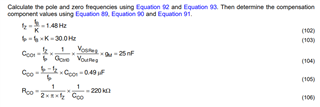
Uli is out so I will cover for him. To reach the 80Hz crossover frequency that Uli mentioned you will need to adjust your COMP values, specifically Rco (R123), Cco (C118) and Cco1 (C120). Please follow the Voltage Loop Compensation section on page 40 of the UCC28056 datasheet (https://www.ti.com/lit/ds/symlink/ucc28056.pdf).
Repeat the same steps from page 40-42 to find the 3 component values except set Fb as 80Hz. The datasheet example uses a Fb of 6.66Hz.