This thread has been locked.

If you have a related question, please click the "Ask a related question" button in the top right corner. The newly created question will be automatically linked to this question.

TPS27S100: TPS27100

Part Number: TPS27S100

Hello,

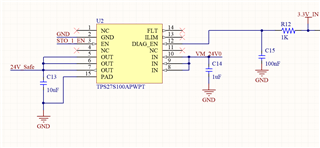
I designed a STO circuit for a BLDC motor driver. I took reference from your TIDA design and I used TPS27S100APWPT IC. But it doesn't work effectively. I connect 24V to IN pins. When I connect 3.3V to EN and DiagEN pins I see 2V on the outputs instead of 24V. So I tried it again after dismounted the IC from driver, but I got the same results. Can you describe me what I'm doing wrong or the things that I need to be carefull before testing the IC?

Thank you.

  • Hello, 

    Could you please share your schematic and waveform?

    Is it possible you are measuring the output with a 10x probe? A 10X probe reduces the input signal to 1/10th of the signal’s amplitude at the scope input.

    Best Regards, 

    Elizabeth 

  • Hello Elizabeth,

    Thank you for your interest. Yes, I can share the schematics. What I want is, in case of an emergency, the microcontroller should produce a 3.3V signal, and the TPS27S100A IC should cut off the power supply to the motor driver. Here are the schematics. I created them based on the STO board designed by TI, called TIDA. 


    Actually, I measured the voltage using a multimeter. I measured 24V on the IN pins (the power input pins of the TPS27S100A). However, on the output pins, I observe 0V in both cases, whether the EN pin is high or low. I also tried testing the IC alone by soldering wires to its pins, and I measured 2V when the EN pin is high.
    The output pins of the TPS27S100A are connected to the supply pins of the DRV3205. I also cannot see 24V on the supply pins.

  • Hello, 

    I would recommend using an oscilloscope to observe EN, IN, OUT, and FLT. 

    It is possible either the EN signal is between its VIL and VIH thresholds shown below or thermal shutdown is being triggered. In between VIL and VIH, we cannot confirm if the device is ON or OFF, meaning the device could also be partially ON. 

    Additionally, we recommend if ILIM is not used, to pull ILIM pin to ground. Floating ILIM could cause a thermal shutdown event where the device will disable even when EN>VIH due to the temperature exceeding TSD. 

    Once you have collected the waveforms, we'll be able to see whether EN is between VIL and VIH or if thermal shutdown is being triggered by observing the voltages on EN and FLT when IN is 24V and OUT is 0-2V.

    Best Regards, 

    Elizabeth  

  • Hello Elizabeth, 
    Thank you for your help. I'm happy to say that when I connect the ILIM pin to GND the TPS27S100A IC has worked correctly. 
    Best Regards

  • Hello, 

    Happy to hear that solved the issue. 

    I will close this issue, and please reach out if you have any further questions. 

    Best Regards, 

    Elizabeth