This thread has been locked.

If you have a related question, please click the "Ask a related question" button in the top right corner. The newly created question will be automatically linked to this question.

TPS2597: Design review. eFuse is broken after a trip

Part Number: TPS2597

Hello,

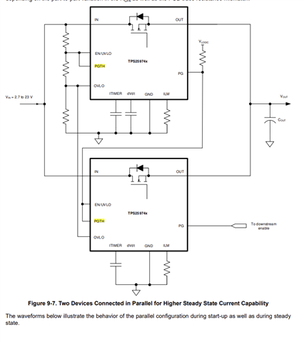
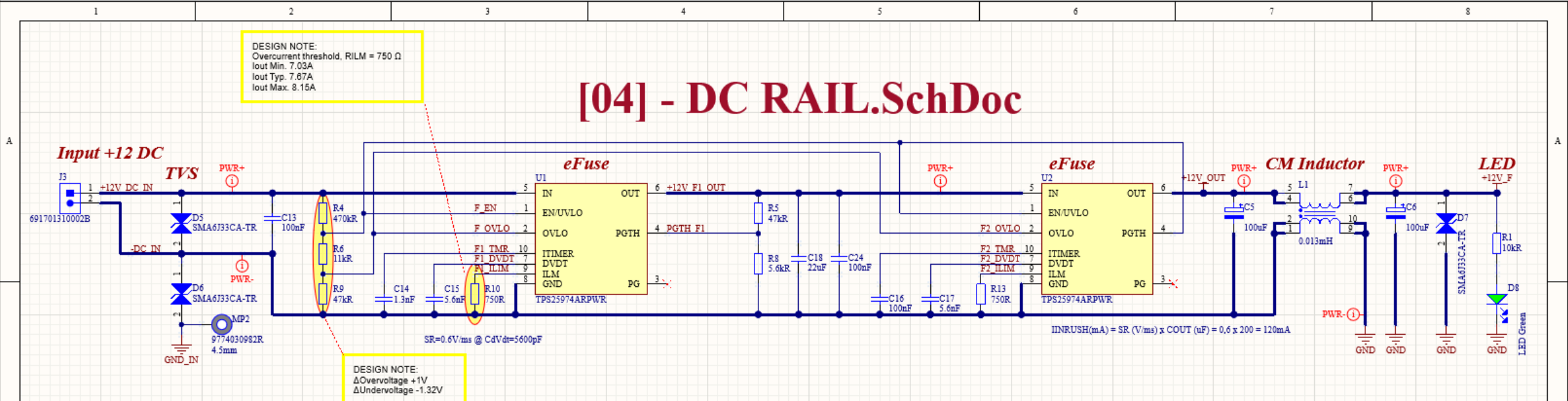
we designen a board with two eFuses in series to meet the one failure requirements. So if one fuse wouldn't trip in a case of overcurrent, the second fuse should do.

As soon as we test a short circuit / overcurrent, the circuit interrupts the current flow. But after removing the (over-)load it doesn't recover anymore. By bridging the fuses on defective board, we found out, that it varies which fuse has been burned.

We tested the circuit with electronics load and with normal high power resistors of 2Ohms to be sure there is no overload caused by the internal input capacitor inside of the e-load. So one 2Ohm resistor for normal operation and a second 2Ohm resistor in parallel to initiate an OC event.

The fuse breaks without a smoke or sparkle.


There are 4 more 22uF capacitors, which are not in the schematic above. 

What could be the issue in this circuit?

We are ware of floating PG signal, but could it cause this kind of damage to the fuse?


  • Hi Alek,

    Generally such fail is due to device VIN abs max violation due to VIN overshoot. You will need to choose an input TVS such that it clamps below abs max of 28V of TPS2597.

    You can use a TVS in between and replace input TVS 33CA with something like 14CA.

    Regards

    Kunal Goel

  • Hi Kunal,

    thank you for your fast response. 
    In the meantime we actually added a TVS Diode SMBJ16A-13-F and 22uF/25V on the input of U1, a schottky diode B330A-13-F on the output of U2, the same way it has been done on the evaluation board and  the fuse doesn't break now. 

    What would you say regarding the overall circuit and the daisy chain with two circuits? Especialy pins U2 pins EN, UVLO and PGTH?

    Furthermore, we don't have any logic voltage on the board, so we left the PG pins open. Could this cause any failure in the future?

  • Hi Alek,

    Yes PG open is fine. Why is PGTH of second eFuse biased to VIN of first eFuse and not VOUT of second eFuse?

    Regards

    Kunal Goel

  • Hi Kunal,

    a very good question. We started our schematic from the application note with two fuses for a higher current. The Pins PGTH and EN were tied together and connected to the first voltage divider.


    But now I wonder if we need the PGTH circuit at all, since we don't use the PG Pins? According to the block diagram there are no further purposes, why the voltage on PGTH must be checked.

    Best regards,

    Aleksej