Other Parts Discussed in Thread: INA190
Hello,
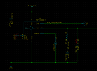
I am monitoring the 3.3 and 12 Volt power supplies to a PCIe card. I'm using INA190A1 current sense amplifiers to amplify the voltage drop across a sense resistor for each current monitor: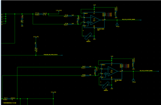
The outputs of these current sense amplifiers are connected through 200 Ohm resistors into pins H1 and H2 (AMON 19 and AMON 20) of the UCD90320: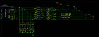
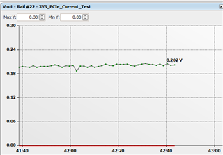
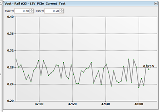
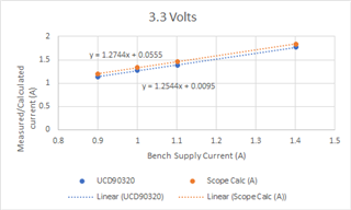
Now in TI Fusion, I'm reading 1.3 and 1.5 times the current (for 3.3 Volt and 12 Volt supplies, respectively) that is indicated when the board is powered from a bench power supply. If I put a DMM or oscillosocpe on TP24 and TP25 of the first schematic I've uploaded (output of the INA190A1 amplifiers), I similarly measure voltages which correspond to 1.3 and 1.5 times the current indicated by the bench power supply.
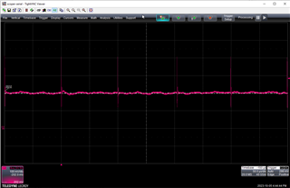
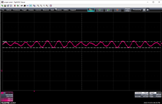
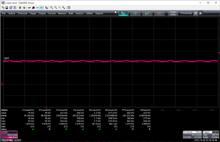
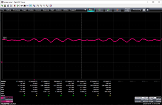
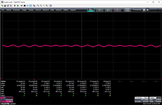
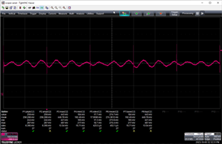
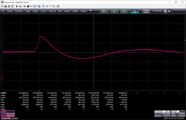
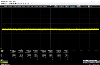
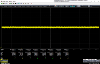
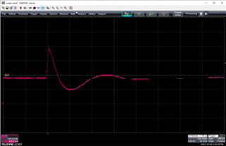
Worryingly, the 3.3 Volt amplifier output has a 10 kHz periodic spike on TP24 with a 300 mV peak-to-peak measurement, but the 12 Volt signal looks clean.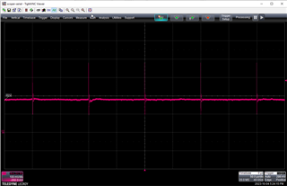
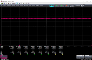
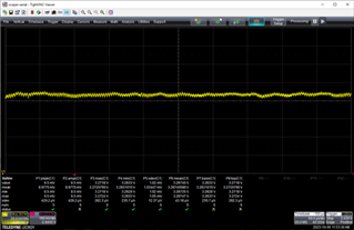
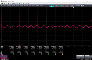
If I remove the 3.3 Volt current measruement from the TI Fusion designer project, then the spikes disappear on the 3.3 Volt line, but then appear on the 12 Volt line.
If I remove both the 3.3 Volt and 12 Volt current measurements from the TI Fusion designer project, then the spikes disappear on both waveforms.
According to the datasheet, "Current monitoring ADC channels are monitored at 200 μs per channel". I therefore have reason to believe that this is caused by the UCD90320 ADC sample and hold.
May I ask the following questions:
May I ask the following questions, please?
- Why is the UCD90320 causing such large spikes on the 3.3 Volt current amplifier output?
- Why is this only present in 3.3 Volts, but not in 12 Volts?
- Why does this effect then present itself to 12 Volts when I disable the 3.3 Volt monitoring?
- Why is the output accuracy of the INA190A1 devices so poor compared to the bench power supply indicated current?
Any help in this matter would be greatly appreciated.
Many thanks!