This thread has been locked.

If you have a related question, please click the "Ask a related question" button in the top right corner. The newly created question will be automatically linked to this question.

TPSI3052-Q1: Active Pre-charge design

Part Number: TPSI3052-Q1
Other Parts Discussed in Thread: TIDA-050063,

Hi Expert, 

I refer the design guide TIDA-050063 High-Voltage Solid-State Relay Active Precharge

Below is my design Sch, 

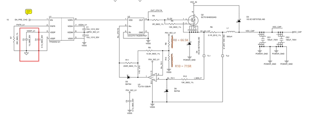
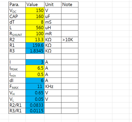
Currently, I set the Ipeak to 3A, Imin to 0.5A, and adjust the R8 to 66.5K, R10=715R, R9=13.3K, the CAP is only 160uF now. 

And below is thee test result. 

Vin = 50V, The result seems good and I measured the Inductor current, the Ipeak and Imin is closed to my design parameters.


But when I increase the input, 

Vin = 100V, the result seems to be some problem


Vin = 150V, there are 3 ramp up steps, seems to be abnormal. 

Please help me to clarify this issue. 

Thanks 

  • Hi Alan,

    Thank you for the question! Our team is looking at the schematic and graphs but we need more time to complete our analysis. We will get back to you tomorrow, October 6, by the end of the day. Sorry for the wait!

    Thanks,

    Sam Skranak

    Product Marketing & Applications | Solid-state relays

  • Hi Samuel, 

    I think I solved this issue. 

    I modify the C2 to 30uF, R8 to 162K, R10 to 1.82K, and this is my design parameter and calculation result. 

    The result seems to be good and similar to the guide. 

    However, I still have some problems, If I increase the CAP to 840uF, the issue will happen again, 

    Seems related to the tRescovery, and I think it should be related to the CVDDH and CVDDM, right ?

    And my typ DC is 220V, max is 260V, How could I solved this issue if I want to increase the CAP. 

    and from the design guide, I cannot understand how to select the Ipeak, and what's the relationship between Ipeak, Imin, and Iaverage? 

  • Hi Alan,

    I will start off by addressing some things that may be the issue and then finish by answering your questions.

     1. Device Mode

    Can you please confirm you are using the TPSI3052-Q1 in three-wire mode (VDDP_U1 = 5V)? 

    Two wire mode may not be able to transmit enough power for this, which is why we chose three-wire mode in the reference design.

     2. Resistor R5

    Another potential issue in your schematic is resistor R5. With 10K we are constantly drawing an additional 1.5mA. In the reference design, this was chosen to be 100K intentionally to limit power dissipation across the resistor. We recommend raising it to 100K.

     3. Your questions

    Glad to see you fixed the cap value for C2. If the issue is happening again it may be because the device is not transmitting enough power across the barrier and it is entering a UVLO state. As you increase the voltages, it will take more power to pre-charge the caps. If you shrink the margin between Ipeak and Imin, the TPSI3052-Q1 will be switching faster and as a result need more power and may be hitting its upper limit. We recommend maximizing the margin between Ipeak and Imin for this reason, which is why 0.5A to 8A was selected in the design guide. Here is the equation to calculate how high your switching frequency can be:

    Fmax = Vbat/(4 * L * dI)

    Where Vbat = battery voltage, L = inductor, dI = change in current or Ipeak - Imin.


    To  answer your second question:

    What's the relationship between Ipeak, Imin, and Iaverage? 

    Iaverage is the amount of current needed to charge the caps in the span of time you chose.

    Iaverage = C*dv/dt

    Ipeak and Imin are determined by the hysteresis thresholds VH and VL, respectively. VH is the threshold where the comparator goes 1->0 an VL is the threshold where the comparator goes 0->1. The hysteresis thresholds are dependent on the Rshunt as well as the resistors R1, 2, and 3 in the design.


    Let me know if this helps!

    Sam Skranak

    Product Marketing & Applications | Solid-state relays

  • Hi Samuel, 

    1. Yes, I use 3-wire mode. 

    2. OK, I'll modify R5 to 100K.

    3. Understood. 

    Thanks for your explanation.