This thread has been locked.

If you have a related question, please click the "Ask a related question" button in the top right corner. The newly created question will be automatically linked to this question.

TPS92692: TPS92692

Part Number: TPS92692

Hi TI Team,

Need to Pass CISPR25 Class 4 in conducted emission test for the TPS92692 IC.

I build a SEPIC converter to drive LED with TPS92692Q1. (refer to EVM schematic)

Input voltage =8~18V

LED = 4LED in series (VF=3.1~3.6V)  ILED=1A

Ris = 0.0047R / RT= 22K / C_DM = 100nF

Design is working fine during normal mode of operation with the respect of the input voltage level 8-18V.

CONDCUTED EMISSION TEST : CISPR25 CLASS 4 - But i am facing issue with the frequency range of 55mhZ to 108mhZ. The dB limit is to pass for this range is 24dB average limit.

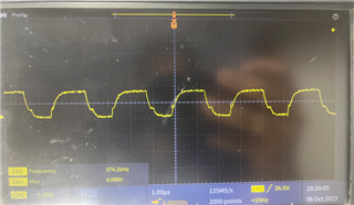
The level i have archived from frequency range is 55mhZ to 108mhZ is 26dB. But i have little bit concern regarding Mosfet gate resistor i have change from 10ohm to 50ohm and the level of the dB is reduced by 8dB with out change in mosfet gate resistor i have observed 34dB but after changing resistor value 50ohm the dB limit we have achieved 26dB.

This is ok from design point of view and what is the limit to tune this gate resistor. As per the data sheet i have to fix this resistor to 12ohm. I am attaching the image for refrence.

What would be the impact that we are facing for changing this gate resistor to 50ohm.

DO you have any calculation for the gate power resistor.

Kindly provide your valuable feedback regarding this point.

Best Regards,

Pankaj Talwar

  • Hi Pankaj, 

    Our experts in China are on holiday this week.  Please expect delay in response.

    Best regards,

    Dave

  • Pankaj,

    The image of gate driver resistance you have listed here is the internal drive resistance of the TPS92692 not the external resistance that you are adding.

    The added gate resistance will slow down the switching of the FET and therefore slowing down the switch node voltage.  It is this switch node voltage rising and falling edges that is mostly responsible for the EMI.  But when you slow this switching edge down the switching loss is higher on the power FET.  How much power loss depends on the FET that you use and the gate resistance along with the switching voltage.  You can measure this additional power loss by comparing the input power with the 10 ohm vs the 50 Ohm.

    Another way to slow down the switching edge is to add a snubber (RC) to the drain of the FET to ground.  Start out with 1000pF and 10 Ohm to see if it helps.  If it helps but not enough, then raise the capacitance to higher like 2700pF or even higher yet to see if it's enough.  You might also need to decrease the resistance to like 5 Ohm.  Note that there will be power loss in the resistor, and you have to size the resistor properly to handle this.

    Hopefully both the additional gate resistance and snubber will help you reach you specification.  Did you try changing the C_DM cap to different values like 0.022 uF and 0.22 uF to see if it helps any with the EMI? 

    Note that EMI is a system design, layout and external components along with shielding at times

    Thanks Tuan

  • Hi Tuan,

    Thanks for the information.

    We have changing DM .022uF to .22uF but not so much differences in dB limit.

    We have changing RC(snubber circuits) mosfet drain 5ohm and 1000pf then the dB limit is down with the freq range 55 to 108mhZ is 4dB. We have selected Rc(snubber) 10ohm and 1nf in drain as well as source side of the mosfet.

    But i have one concern the gate resistor package is 0603 and value is 10ohm and changing to 50ohm can you tell me the formula for calculating wattage for base resistor, i have seen lot of formula but it will not help in my case. 

    I am attaching image for Gate pulse can you check it' s ok.

    Waiting for your valuable feedback.

    Regards

    Pankaj

  • Pankaj,

    The power loss in the gate resistor is minimal for your application and a 603 package is fine for 50 Ohm gate resistor.  You can measure the voltage differentially across the resistor and calculate the power loss if you want.  This is the easiest way of doing it.  

    Thanks Tuan