This thread has been locked.

If you have a related question, please click the "Ask a related question" button in the top right corner. The newly created question will be automatically linked to this question.

TPS25981: The PG is not correct when output OCP

Part Number: TPS25981

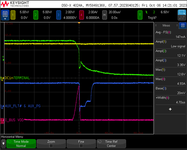
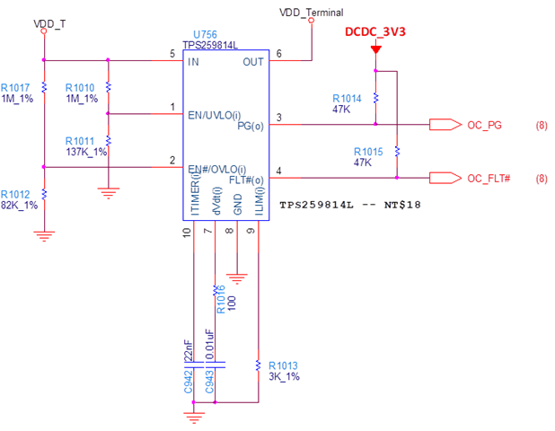
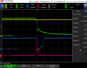
We use TPS259814L for the load switch. The current limit is set to 2A. We test the 10A peak around 3us. We find the PG is not correct, because it goes low at OCP, and waiting 18us then going high. At the meantime, the output voltage is still low. May I learn from you why the PG can't keep low when the output voltage isn't ready?

BR, Gary

Yellow: Input voltage, Green: Output voltage, Blue: PG, Red: Output Current

  • Hi Gary,

    Thanks for reaching out. I will get back by EOD on this.

    Regards

    Kunal Goel

  • Hi Gary,

    1. Please share schematic for review. 

    2. Is this repeatable?

    3. Yellow curve is VIN and Green is VOUT?

    4. You are applying 10A load pulse for 3us through eload?

    Regards

    Kunal Goel

  • 1. Please share schematic for review. 

    G: Attached

    2. Is this repeatable?

    G: No, PG is not repeatable.

    3. Yellow curve is VIN and Green is VOUT?

    G: Yes

    4. You are applying 10A load pulse for 3us through eload? 

    G: They use capacitance load. The 10A peak seems a inrush current. 

  • Hi Gary,

    Schematic looks fine. If it is not repeatable then it is difficult to say much. It could be possible that 3.3V supply to which PG is pulled up is drooping. 

    1. On repeated testing what is the PG behavior? 

    2. Are they hot-plugging cap? 

    3. To get more idea we should probe 3.3V pullup, ITIMER pin, ILIM pin and eFuse input current(to know exact current going through eFuse). 

    Regards

    Kunal Goel

  • Hi Goel,

    1. On repeated testing what is the PG behavior? 

    G: It same as attached waveform.

    2. Are they hot-plugging cap? 

    G: No. It always stay in Vout.

    BR, Gary

  • Hi Gary,

    Thanks for the info. 

    1. Lets try to understand reason for that current peak. Is it due to a downstream load turn on?

    2. Also to understand more we definitely need to probe other signals. To get more idea we should probe 3.3V pullup, FLT pin, ITIMER pin, ILIM pin and eFuse input current(to know exact current going through eFuse). 

    3. Also one more thing could be possible is that PG pin voltage is going negative in waveform and PG pin has negative abs max of 0.3V , crossing that can cause pin to misbehave.

    Regards

    Kunal Goel