Hello Ti, Please help me...thanks a lot.
This thread has been locked.
If you have a related question, please click the "Ask a related question" button in the top right corner. The newly created question will be automatically linked to this question.
Hello,
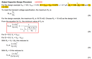
Equation 29 is derived from Equation 26 in the previous section. Equation 26 defines the method for calculating output voltage transient in the case of a provided configuration and load step.
Best regards!
Britton
Hello,
The first part of equation 26 "(L*ΔIo^2)/(2*Co*Vind)" comes from the impact of charge Q passing through the inductor as the current steps down from full load to 0A. As the current discharges linearly, the resulting charge Q = (I^2*L)/(2*V). The output voltage resulting from this charge is Vp = Q/Co, therefore Vp = (I^2*L)/(2*Co*V). The second part of the equation accounts for the device's cycle-by-cycle ripple.
Best regards,
Britton
Hello Britton

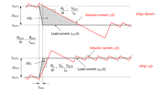
1, I know the first part load step-down: ΔQc*VL=(1/2)*L*(ΔI)^2 and ΔQc=Co*ΔV1, so we get ΔV1=L*(ΔI)^2/(2*Co*VL).
ΔQc*VL=(1/2)*L*(ΔI)^2=(1/2)*L*(Iout1 - Iout2)^2. But, why not ΔQc*VL=(1/2)*L*(Iout1^2 - Iout2^2) ?
2, Please explain further on the second part cycle-by-cycle ripple equation. thks.
Hi,
Please give us some time to dig into this further and get back to you
Thank you for your patience!
Britton
Hello, my name is Peter Miller, I am one of the other applications engineers supporting the LM3000 and assisting Britton Jones.
The Transient equations in the LM3000 datasheet are simplified estimations designed to provide an output capacitance that has a high-confidence of meeting the required transient response once the current mode control loop is compensated later in the design. As such, they include some deliberate over-estimations to account for the non-ideal loop bandwidth response. In addition, there appears to have been an error made in the second term's estimate of the output voltage ripple, which should not have Co in the numoerator.
The first term, as previously discussed, is based on the Charge flow through the inductor as it is fluxed up in response to a load step or defluxed in response to a load drop. You are correct that this term is missing a 1/2 factor, as the average current through the period is ΔI / 2. This is intentional and provides an over-estimation of the output capacitance to account for the control loop delay, which prevents the LM3000 from instantly adjusting it's duty cycle to 100% or 0% when the load changes.
The second term was suppose to be an additional term for the output ripple, to account for the fact that the transient may occur anywhere within the steady-state ripple on the output voltage. It appears there was an error made in the derivation when they attempted to solve ΔVout from equation 25 by substituting ΔIL for for it's components Tsw x VL / L. I would recommend replacing the second term with ΔVout from equation 25, to estimate Vp, or reduce Vp by ΔVout when calculating the minimum allowable capacitance for transient.
Again, this provides a small over-estimation of the required output capacitance so that when the loop compensation is done and the final loop bandwidth is established, the resulting transient voltage is lower than Vp used to obtain the output capacitance. After you have selected Ren, Rcomp and Ccomp going through the compensation section, you can obtain a more accurate estimation of Vp by calculating the output capacitor impedance at the cross-over frequency using the equation:
Zout(f) = Rc + 1 / (2 × π × Fco × Co)
If you are using multiple types of output capacitors, calculate each group of similar output capacitors separately, then add them in parallel using the formula Zeq = 1 / (1/Z1 + 1/Z2...1/Zn)