Hello,
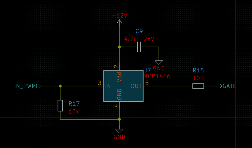
I am using the CSD19538Q2 as a low side switch for controlling a solenoid. I am driving it using an MCP1416 gate driver which can source/sink at 1.5A peak current with a drive voltage of 12.9V at a PWM frequency of 24kHz with an input voltage of 32V.
At a coil current of 300mA, the FET should only dissipate a few dozen mW, yet it appears to heat up to >70 degrees. I have tried altering the PWM frequency down to 4kHz and the end temperature is the same.
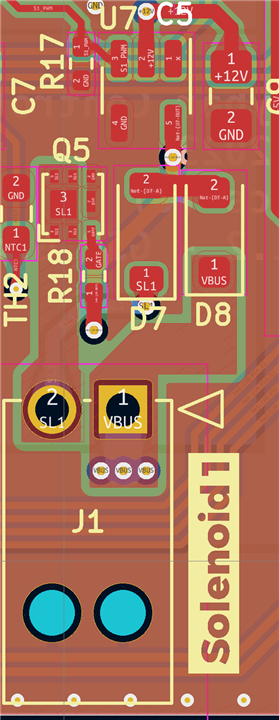
Below is the relevant parts of the schematic, initially I had a 10R resistor on the gate, but replacing it with 0R didn't make a difference.
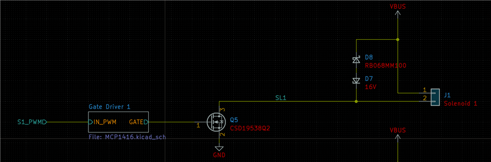
I am unsure as to why the FET is dissipating more power than expected, any help is appreciated.
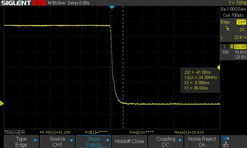
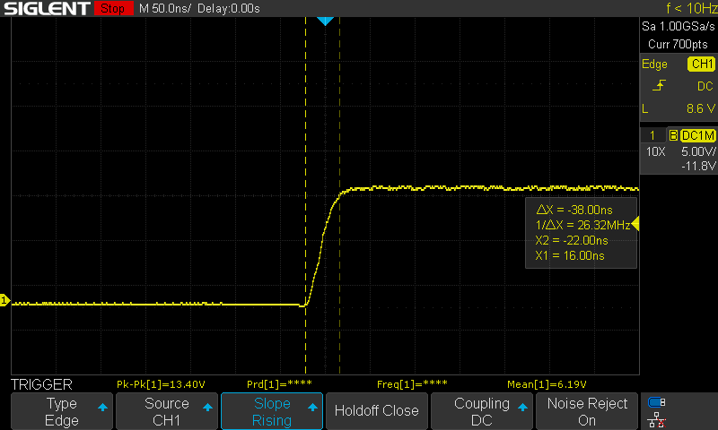
Attached in addition is the switching waveform at the FET gate, and the switched voltage at the drain. All captures are done at 24kHz, coil current 0.35A with a gate resistance of 0R.
Gate switch on:
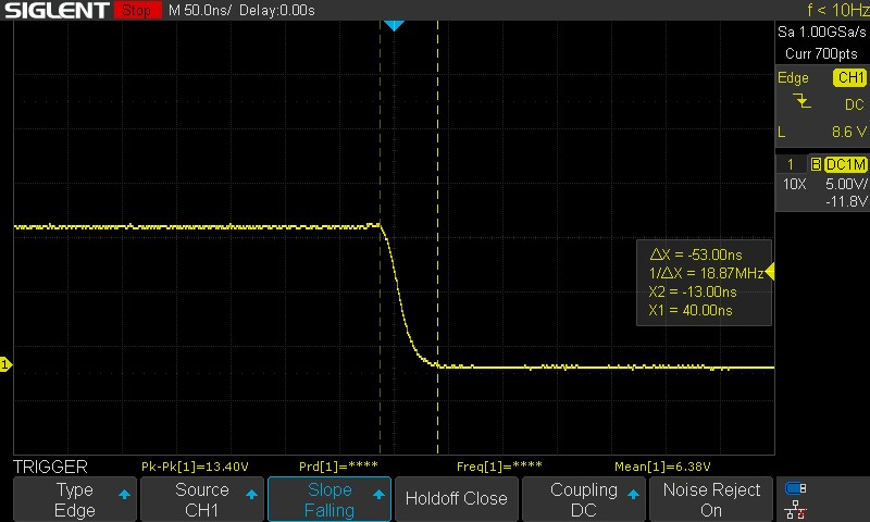
Gate switch off:
Drain voltage at switch off:
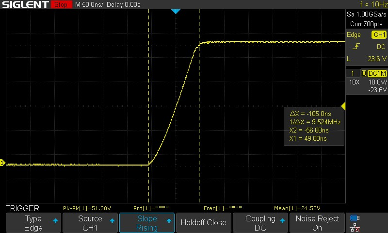
Drain voltage at switch on: