This thread has been locked.

If you have a related question, please click the "Ask a related question" button in the top right corner. The newly created question will be automatically linked to this question.

BQ28Z610: BQ28Z610

Part Number: BQ28Z610
Other Parts Discussed in Thread: EV2400

Hi,

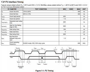
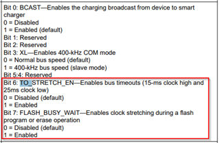
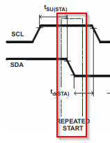
We are using the BQ28Z610 fuel gauge in a battery design, used in one of our products.  We are currently having issues communicating with the fuel gauge over I2C, in high-speed mode (400kHz).  We are able to communicate OK at 100kHz using our product. We can communicate OK at 100KHz and 400kHz using the EV2400 eval module.  We have used the EV2400 to set the XL bit in I2C Configuration but doing this seems to cause the I2C bus to hang on our product setup, when running at 400kHz.

Can you please provide guidance? I have read about several people having issues with the 400kHz mode on this IC

Thanks,

Robert White

  • Hi Robert,

    Can you please provide context in the way you are using the high-speed mode?

    The main purpose of the high-speed mode is to allow quicker programming of the gauge during production. We do not recommend using the high-speed mode during regular operations.

    Regards,

    Anthony Baldino

  • Hi Anthony,

    We are using a NXP i.MX7Dual processor on a Main PCBA to communicate with the fuel gauge.  The fuel gauge is in a self-contained battery which plugs into the Main PCBA.  We are trying to communicate normally with the fuel gauge at high-speed, as everything else on the bus runs at this speed.  Is there any reason why you do not recommend high-speed mode for regular communications?

    Thanks,

    Robert

  • Hi Robert,

    We have found success in this diagram below when dealing with issues with high speed mode. As long as the data and clock structure are the same as the diagram below, it should work properly.

    Please let me know if this helps.

    Regards,

    Anthony Baldino

  • Hi Anthony,

    I'm working with Robert to get this chip working. We've got the chip working at 100KHz, then tried to set the bit to work at 400KHz and it lockup after this transfer.


    Note we do not have to do actually run at 400KHz to make this happen, it seems to be that if we set that bit, then try and use it, reading the status seems to lock it up completely even at 100KHz in a previously working system. I can see this on two seperate devices that both fail in an identical way. Do you have any suggestions?

  • Hi Nicholas,

    This could possibly be a clock stretching issue.

    Could you tell me how these bits are currently configured?

    Regards,

    Anthony Baldino

  • Hi Anthony, 

    These bits are currently configured as default (both 0)

    Do we need to change these if XL is set high?

    Thanks,

    Robert

  • Hi Robert,

    Setting Bit 6 is worth a try, however Bit 7 should always be low.

    Also, after taking a look at the data sent earlier, we saw that the final signal is possibly not working because it isn't meeting the start condition seen below where SDA needs to have a falling edge while SCL is high to begin the process seen here:

    Regards,

    Anthony baldino

  • Hi Anthony,

    Are you talking about the last data read in that capture I took? The part where it reads 0x00.
    I don't think a repeated start should be there and we don't see your tool generating this either.

    Here's some trace we capture from your tool

    We don't control the SDA line in this situation so I'm not sure what we can do from the host side to resolve it. It's too frequent to reset the bus

  • Hi Nicholas,

    Is it possible for you to send a scope capture of the data being read?

    We think one of the timing requirements from the chart above might be getting broken and are trying to narrow down which it is.

    Regards,

    Anthony Baldino