This thread has been locked.

If you have a related question, please click the "Ask a related question" button in the top right corner. The newly created question will be automatically linked to this question.

TPS546D24A: Anti-Resonance

Part Number: TPS546D24A

Hi,

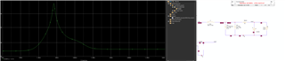
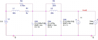
I'm running the PDN impedance of the transmission system. I need to define the three frequency regions based on the frequency of the largest antiresonce of the power supply impedance. So, could you please provide anti-resonse response to the TPS546D24A?

Regards,

Gajendiran A

  • Hi Gajendiran,

    What do you define anti-resonance to be? Is this where the output impedance has peaks?

    This device has an average PSPICE model available that you can simulate a frequency response.

    Thanks,

    Joseph

  • wanna define an impedance mask for different frequencies based on antiresonance frequency
    Please share the link to download the model and why this is called the average PSPICE model. Is there a different model with min and max?

  • Hi Gajendiran,

    Here is the link to the Average PSPICE model: https://www.ti.com/lit/zip/slum705

    The average PSPICE model enable you to run AC analysis with the converter to find things like bode plots and frequency response plots.

    The transient PSPICE model isn't able to run AC analysis, only transient.

    It may also be able to help find the antiresonance frequency you are looking for here.

    Thanks,

    Joseph

  • Thank you for your fast response, Could you please share the transient PSPICE model also?

    Which model helps to simulate antiresonance frequency?

  • Linked the transient model: https://www.ti.com/lit/zip/slum707

    The average model is able to simulate output impedance, which seems to be where you measure the anti-resonance frequency?

    Are you considering the anti-resonance frequency as the cross-over frequency of the power supply, it would be the frequency at which the output impedance is highest?

    Thanks,

    Joseph

  • Are you considering the anti-resonance frequency as the cross-over frequency of the power supply, it would be the frequency at which the output impedance is highest.
    Yes, I am looking for the highest output impedance over a frequency. How to do this?

    I ran avg model simulation, and I can't see impedance changes. Please look at the image below and let me know if I'm missing something here.

  • Hi Gajendiran,

    You'll need to modify the AC simulation because the default measurement is for the loop gain and phase.

    Setup the DC current load at the output, then put an AC current source in parallel. 

    Then you'll want to get a plot of Vout/(IDC+IAC) vs. frequency which should be a measure of output impedance.

    Thanks,

    Joseph

  • I expected the anti-resonance to be above 100MHz Maybe I will run with the actual board and I will see.

    Vout/(IDC+IAC), Why you added IDC+IAC? I have added only I2 as V(VOUT)/ I(I2) Please see in the above circuit.

  • I think we are talking about 2 different things then. The average model is only accurate below the switching frequency, which 100MHz is well above.

    The Vout we are measuring contains both DC and AC components, which is why I included IDC+IAC.

    Thanks,

    Joseph

  • Hi Joseph,

    We discussed the VRM model earlier, and you provided the VRM schematic below,

    I have an S-parameter model of the board, which includes (All caps Except inductor). So, could you please give me a VRM model without output caps? I need to do a joint analysis of VRM+PCB+Package+Die.

    If possible, Please share the S-parameter of VRM(without output caps).

  • Hi Gajendiran,

    We don't currently support an S-parameter model for this device.

    The PSPICE model we have available is for evaluating the device functionality and not an exact implementation. 

    Thanks,

    Joseph

  • Hi Gajendiran,

    I'm closing this thread out since we answered it over a call.

    I also realized that when I ran the sims it doesn't affect the impedance measurement if you use IDC + IAC in PSPICE, so you can continue using Vout/IAC for output impedance.

    Thanks,

    Joseph

    -If this resolved your issue please click, "This resolved my issue" Thanks!