This thread has been locked.

If you have a related question, please click the "Ask a related question" button in the top right corner. The newly created question will be automatically linked to this question.

BQ25798BKUPEVM: User Guide Steps Issue

Part Number: BQ25798BKUPEVM
Other Parts Discussed in Thread: USB2ANY

Dear TI,

I hope that you are doing well. I have successfully connected the USB2ANY with BQ25798BKUPEVM through cloud application.

The issue I am facing right now is the configuration of EVM kit by following the USER GUIDE steps for cloud platform.

The EVM is not working according to the given User guide steps.

I am looking forward to the solution for it.

Regards,

Ahmed Ali

  • Hi Ahmed,

    Which steps are inaccurate?

    Regards,

    Jeff

  • Hi Jeff,

    I did the configuration and register setting of EVM according to the TI cloud GUI as given in user guide but the EVM response is not according to that! 


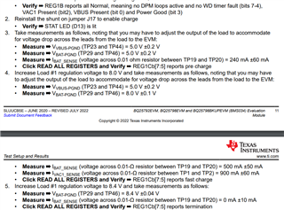
    EVM response should be like the following


    I am have set the 5V 3A power supply at the input and DC load (200W) in CV mode set at 5V. The output charging voltages I am getting right now are ~2.2V. 

    The status in gui for EVM is the 'Not Charging".

  • Hi Ahmed,

    Do you have a battery or battery simulator attached at BAT pin? If not and charge is enabled from /CE pin and CE register bit, the SYS and BAT outputs pulse up and down as the charger charges/discharges/recharges the small output capacitors on BAT.  The SYS output of the charger is designed to regulate to MINSYS voltage < CV until the battery reaches that voltage and then follow the battery up to the CV voltage.  If you are expecting a 5V output at SYS and 4.2V battery at BAT, that is not how the IC was designed to operate.

    Regards,

    Jeff

  • Hi Jeff, I am using the DC Electronic load at the BAT pin. I do not have the battery simulator. The user guide mentioned to use the DC load which I have attached to it. 

    What steps should be taken to use the DC electronic load instead of battery simulator?

  • Hi Ahmed,

    The DC electronic load must be set to CV mode with the CV level at the battery voltage you want to simulate.  A DC power supply should be attached is parallel set to a voltage lower than the CV mode level in order to pre-bias the electronic load.  When enabled, the charger's charge current replaces the DC power supply current.

    Regards,

    Jeff