A related question is a question created from another question. When the related question is created, it will be automatically linked to the original question.
If you have a related question, please click the "Ask a related question" button in the top right corner. The newly created question will be automatically linked to this question.
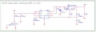
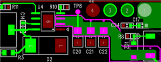
For your application, you can refer to our EVM to design layout. For the schematic, the output can add another 22uF capacitor. In addition, a 0.1uF capacitor should be placed between the VIN pin of the chip and ground, and should be as close to the chip pin as possible when laying out the PCB. Thanks.