This thread has been locked.

If you have a related question, please click the "Ask a related question" button in the top right corner. The newly created question will be automatically linked to this question.

USB-PD-CHG-EVM-01: TPS25750 I2Cs failure to ACK

Part Number: USB-PD-CHG-EVM-01
Other Parts Discussed in Thread: TPS25750

Project – Develop a USB-C PD to supply 5V 3A using USB-IF certified components.
1. I have the TI USB-PD-CHG-EVM-01 integrated Type-C PD Evaluation Module and have been able to program it with the Aardvark I2C programmer to deliver the 5V to the USB-C connector.
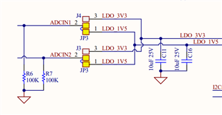
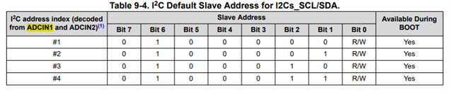
2. I have not been able to program the TPS25750 device on my Test Fixture. There isn’t an Ack on the I2CS signal. There is supplied 3.3V and 5V and resulting LEO_3.3 and LDO_1.5
3. To verify the Aardvark I2C interface, I am able to program the EEPROM directly, but the TPS25750 doesn’t react.
Can you suggest any design changes or steps to get the TPS25750 to operate?
Thanks for your help.USBC Test Fixture.pdf

  • Hi Bruce,

    I took a look at your schematic and the I2Cs signals are routed correctly.

    I know it seems trivial but please make sure you did not accidentally swap the SDA and SCL lines when connecting to the header.

    What I2C address are you using when trying to talk to the TPS25750 over I2Cs using the Aardvark? Your ADCIN I2C address is set to 0x21.

    Best,

    Alex

  • Alex, Thanks for responding.  I am using the Aardvark address 0x50.  I have checked the SDA and SCL lines several times.  I just swapped the two and it didn't make a difference.  I can program the EEPROM (A0,A1,A2 are gnd) directly from the Aardvark while it is.  I have built up two PCBs with the same results.

    I can program the TI EVM PCB.

  • I am not sure where you got the 0X21 ADCIN address, but I tried it, and it programs but the verify fails.  I do get 5V at the Connector.

  • Alex I was able to program my device using the Aardvark address 0x21, however it failed verification.

    My device does now supply the 5V.  Where does ADCIN IC2 address of 0x21 come from?  Any Idea why the verification is failing?

  • Hi Bruce,

    In your schematic, with the indicated jumper configuration, you are shorting ADCIN 1/2 to LDO_1V5. I2C addresses of the PD controller are set by the ADCIN configuration. The options are 0x20, 0x21, 0x22, 0x23.

    0x50 is the I2C address for the EEPROM.

    When you program your board, please keep in mind that the I2C addresses of the PD controller and the EEPROM are not the same. To talk to the PD controller over I2C, you must use the PD's I2C address, which is 0x21 in your case.

    Can you send me an I2C log of your test for communication with the TPS25750 PD controller on your test fixture board? When verify fails, does the PD still work as expected according to your project configuration?

    Best,

    Alex

  • Thanks for your help

    0-4 TPS25750 address 0x50          Immediate fail

    5-9 EEPROM directly                       Pass

    10-15 TPS address 0x21                 Pass but fail verify

    #1 When I flash the TI EVM Text fixture with address 0x50 using Test.bin, the clock and data are passed on to the U5 EEPROM.  I verify that with my o-scope.

    #2 When I flash my PCB with address 0x50 using Test.bin, there is no data passed thru the TPS25750 to the EEPROM. Verified with o-scope.

    #3 If I then flash my test PCB EEPROM directly with address 0x50 using Test.bin file, the program verifies, but there is no 5V output. No Data is transmitted at power on.

    #4 If I then flash flash my test PCB TPS25750 with Test.bin, address 0x21, it programs does not verify but I get do get the 5V output. Data is transmitted at power on.

    Note: I have not tried to program the TI EVM using address 0x21.

    I am using theTPS25750 Application Customization tool to generate my Test.bin file.  Is there a different file that is to be used to program the TPS25750?

  • Hi Bruce,

    The I2C address of the TPS25750 is 0x21, the I2C address of the EEPROM is 0x50. 

    When flashing the EEPROM directly, you should use address 0x50. For all other cases (patching to PD and flashing to EEPROM through PD), you must use address 0x21. 

    When you generate the binary file from the Application Customization tool, please make sure you generate a full flash binary. Also, you can try "Erase" on Aardvark before "Program+Verify". Sometimes erasing first helps the verification succeed.

    Best,

    Alex