


Dear TI’s Engineering Team,
We have designed a BMS with BQ7695202 as the AFE and STM32 L4 based MCU. Currently we are using a 0.5 milli Ohm sense resistor to measure the current and we are using high side MOSFET switching with the sense resistance placed on the low side. As per the datasheet and technical reference manual (TRM) of BQ76952, we have configured the AFE for a short circuit threshold of 40 Amps with the SCD threshold set to 20mV (refer to Fig 2 for the threshold settings) and the SCD delay set to 1 (fastest setting with no delay). The settings are shown in Fig 1. The setting of SCD delay to 1 should result in the detection of the short circuit within nano seconds as per the TRM (refer to Fig 3 and Fig 4) and should result in the DSG MOSFET cutoff. However, this is clearly not the case as we are observing upwards of 8uSec delay when performing the short circuit test with load.
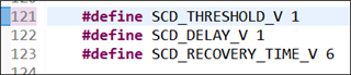
Fig 1. Firmware settings for SCD control
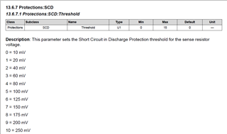
Fig 2. SCD threshold configuration description from page 182 of the TRM
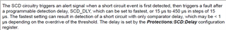
Fig 3. SCD functionality as per page 38 of TRM
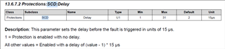
Fig 4. SCD detection delay configuration description from page 182 of the TRM
Furthermore, the TRM suggests the configuration for DSG FET Protections A to be set to 0x80 or 0XE4 for the fastest turn-OFF as shown in Fig 5. These configuration settings have been applied in the firmware as well and it is shown in Fig 6.

Fig 5. DSG turn-OFF configuration specification as per page 34 of the TRM
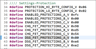
Fig 6. DSG turn-OFF configurations applied the firmware
The circuitry for the DSG control from the current schematic is shown in Fig 7.
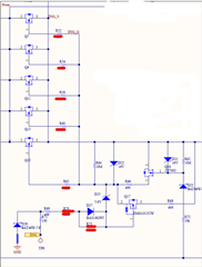
Fig 7. DSG MOSFET control circuitry as per the current schematic
Note that R70 and R73 are shorted in the current schematic and the resistors R52, R54, R58, R60 and R65 are of 10 Ohms. In our case, the series gate resistance across the DSG pin and DSG FET is approximately 610 Ohms and as per the datasheet’s mention (Fig 8 ) of the resistance at DSG FET’s gate shows that it is lower than 1K Ohms.
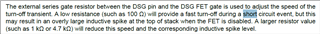
Fig 8. Description of MOSFET turn-OFF speed during SCD at page 72 of datasheet
As per the example given in the datasheet (refer to Fig 9), the detection delay is supposed be in nano seconds for voltage of 25mV across the sense resistor.
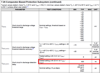
Fig 9. Example of SCD delay from page 22 of the datasheet
The voltage level in our case would be 40mV, which is far greater than 25mV and hence as per the datasheet’s version, the detection delay should have been much lower. This is, however not the case as the captured waveforms from the scope show it to be greater than 20uSec once the current starts rising. The detection delay is shown in Fig 10.
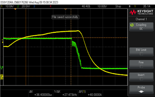
Fig 10. Capture from scope shows the time delay between the load current (yellow waveform) exceeding 40Amps and the point where the MOSFET’s VGS (green waveform) starts dropping
Furthermore, we have re-evaluated the same test by completely disconnecting the mosfets from AFE and probed the DSG pin with respect to ground to ensure there is no delay from the mosfet side.
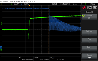
Fig 11. Delay of 13 uSeconds with green waveform indicating the voltage across the sense resistor terminals and the blue waveform being the voltage of the DSG pin of AFE with respect to ground
Here, the voltage across the shunt resistor is changing from 150mV to 250mV. The SCD threshold setting was 200mV. In the above figure (Fig 11), it can be clearly seen that AFE is taking 13us to react to the short circuit even with the fastest setting
Note: The OCD protections were disabled during this test and only SCD was enabled
We request the TI’s team to help us with this. We want to reduce the short-circuit detection time to the least possible value as this is one of the most critical aspects of our BMS.
Thanks in advance.
