This thread has been locked.

If you have a related question, please click the "Ask a related question" button in the top right corner. The newly created question will be automatically linked to this question.

BQ79616-Q1: BQ79656-Q1

Part Number: BQ79616-Q1
Other Parts Discussed in Thread: BQ79656-Q1, BQ79616

HI 

We are using BQ79656-Q1 as base device and six BQ79616-Q1 ics subsequently.

We were testing balancing feature on the seven balancing ics.

We had kept it in auto balancing mode on all channels with 5 second duty ratio.

We have found that in each balancer ic the current drawn with different pattern.

Sharing the images of the pattern below:

Balancer 1 - Single channel waveform

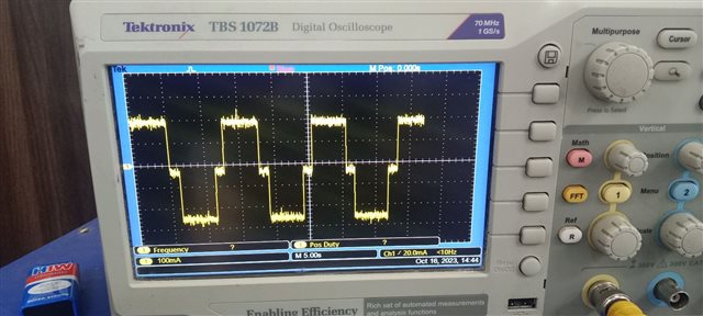
Balancer 1 - current on one channel

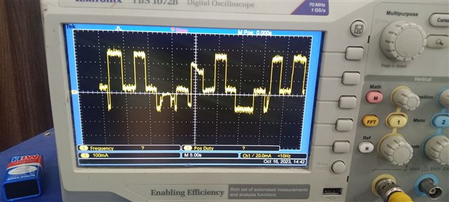
Balancer 2 - current on one channel

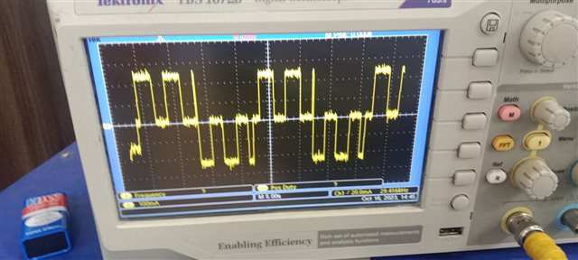
Balancer 3 - current on one channel

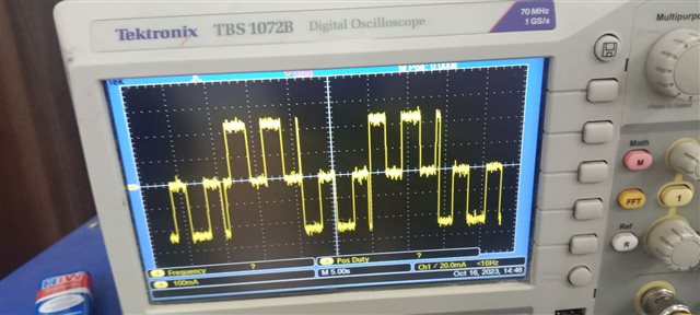
Balancer 4 - current on one channel

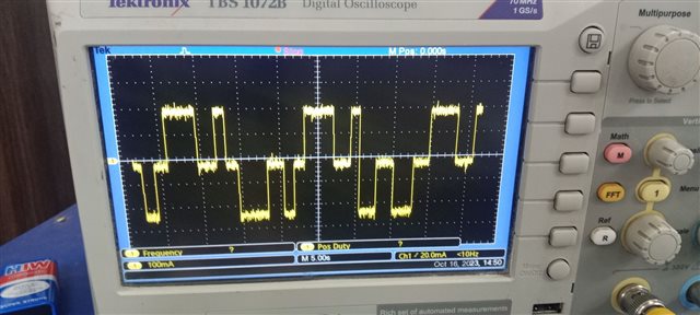
Balancer 5 - current on one channel

Our doubt is why the pattern is different on different balancers?

We are getting appropriate current only in base device but not on other device?

Can you please guide us how to resolve this issue?

Thanks

Ramchandra Bhosale

  • Hi Ramchandra,

    The design of the cell balancing for the BQ79656 and the BQ79616 are exactly the same. This seems to be a difference in PCB design. Could you check or send your Cell balancing circuit design to see if there is any difference between your 656 cell balancing circuit and your 616 cell balancing circuit?

    Regards,

    David

  • HI David.

    We have checked the schematic. The circuits for BQ79656 and BQ79616 are exactly same. We feel that there must be some timing differences for duty ratio between the balancers ics. However we are aware about the difference. Let us know if you get know the answer.

    Thanks

    Ramchandra Bhosale

  • Hi Ramchandra,

    To narrow down the problem on the 616, could you display the current of manual balancing one CBFET at 5s duty cycle?  Could you also display the current of enabling two adjacent CBFETs at 5s duty cycle?

    Regards,

    David