


Other Parts Discussed in Thread: UCD3138A
When I conducted DPWM high-resolution testing on the control board UCD3138ALLCEVM149, I found the following abnormal situations
The test conditions are:
UCD149ALLCEVM3138 Control Board for UCD3138A LLC Evaluation Module
Using TI's LLC half bridge example program, enable unused DPWM 2 modules for testing on this basis
Set the loop value to 100
Events 1, 2, 3, and 4 are set to 0, 2, 40, 50
Change the value of Event 4 to 95 through Debug in the UCD3xxx Device GUI
The testing phenomenon is:
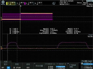


Discovered discrepancies between the high level time values of the unchanged and changed waveforms and the set values
The rising and falling edges of the waveform before the change are: 40, 50, and the value of the high-level time is 5.3ns, set to 2.5ns, with a difference of 2.8ns
The rising and falling edges of the changed waveform are: 40, 95, and the value of the high-level time is 15.9ns, set to 13.75ns, with a difference of 2.24ns
The difference between the two waveforms after comparison is 10.55ns, set to 11.25ns, with a difference of 0.7ns
And when I tested the DPWM wave, I found that the output waveform was not stable, with a jitter of 500ps under infinite afterglow

Regards,


