This thread has been locked.

If you have a related question, please click the "Ask a related question" button in the top right corner. The newly created question will be automatically linked to this question.

TPS25750: I2C_IRQm with BQ25792

Part Number: TPS25750
Other Parts Discussed in Thread: BQ25792, , BQ25750

Hello,

I am interested in utilizing the I2C_IRQ for emergency situations.

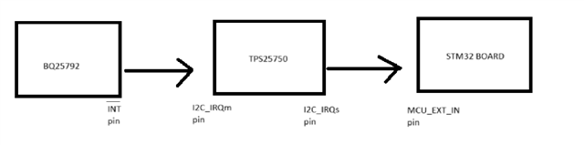
My specific concern is whether there's a viable approach to communicate between BQ, TPS, and the MCU. I understand that the Technical Reference Manual (TRM) illustrates the use of I2C_IRQs pins for communication between TPS and the MCU, but I am seeking a solution for the communication path involving BQ -> TPS -> MCU.

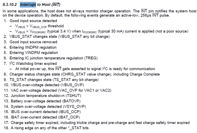
In the given scenario, the BQ25792 triggers interrupts in TPS, which in turn notifies the MCU by setting the INT_EVENT1 register concerning a situation in the BQ registers. To provide a concrete example, I'm particularly interested in monitoring battery overvoltage detection as outlined in section 8.3.10 of the BQ25792 datasheet.

I am sending a transition to clarification.

Your guidance on achieving this communication flow effectively would be greatly appreciated.

Thank you.

  • There is no need to route the IRQ pin through the TPS25750, it is an open drain output and so is the /INT of the BQ25792.

    You can simply wire or the IRQ pins ofthe TPS25750 and BQ26792 directly to the GPIO of your MCU.  You will need to read both the TPS25750 IRQ status register and use the 4CC I2CR command to read the BQ25750 status register to determine which part issued the IRQ and then acct accordingly.

    Regards,

    Chuck

  • Thank you for your response.

    Your suggested approach indeed makes sense. However, I have a question regarding the meaning and function of the I2Cm_IRQ pin. Additionally, I've encountered challenges in configuring the GPIO10 pin to be multiplexed as an I2Cm_IRQ pin. The Technical Reference Manual (TRM) does not provide a clear explanation of the pin's purpose.

  • Azad,

    The IRQ setup for the TPS25750 is based on I2Cs which is labeled as I2C1 in the GUI and is defined by registers 12, 14, and 16 and their definition is based on the TRM section 2.3.  The I2Cm interrupt is not used.

    The Interrupt status is read on register 14.

    The Interrupts are cleared by writing to register 18.  The register is usually fully cleared by writing all zeros, but read modify write can work if you do not have an interrupt queue in your MCU and want to clear interrupts individually.

    The Interrupts that are enabled are set by register 16.  This is an active high mask to enable Interrupts and is defined in the GUI in the Advanced Tab shown below.

    Sorry for the confusing way that the TRM is written.

    Regards,

    Chuck

  • Thank you for your response, Chuck.

    So, does the I2Cm_IRQ pin have no capability to detect interrupts from Slave devices? Why does this pin have input feature? I wanted to learn more about GPIO 10 pin

  • Azad,

    The I2Cm_IRQ pin has the hardware capability to work as an IRQ output, but the functionality was redundant to the  I2Cs_IRQ pin so it was disabled in the supported device firmware. 

    The pin has no function in the current firmware. 

    Regards,

    Chuck