This thread has been locked.

If you have a related question, please click the "Ask a related question" button in the top right corner. The newly created question will be automatically linked to this question.

UCC21710-Q1: Convergence Problem Simulating GateDriver in PSpice for TI

Part Number: UCC21710-Q1
Other Parts Discussed in Thread: UCC21732, UCC21710, UCC21750

Hello,

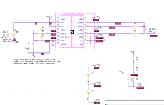
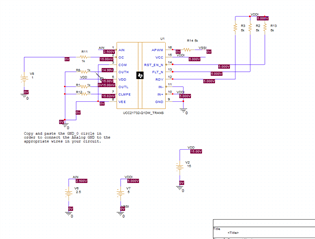
unfortunately I stuck when i am trying to simulate the UCC217xx.

First question is: The Title of the Symbol is UCC21732 but in the Library it is named as 21710. For which driver is this model. Later I want to use the 21755 but there is no model abailable.

My goal is, that I can simulate the OC/Desat protection for my SIC Power Module. I have more expcrience in LtSPice but no in PSpice (for TI)
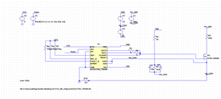
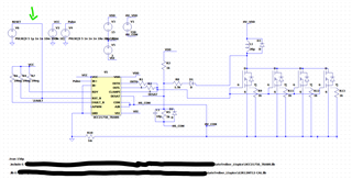
Problem:

With standard PSpice settings, a convergence error is shown. When I play aaround with the settings, simulation runs but infinite slow.

I removed the MosFet, so I can be shure that the GD is the problem.

I attech the simulation files. 

If somebody can help me, I am very happy.

Kind regards.

Philipp 

 Gatedriver_Desat.zip

  • Hi Philipp,

    I have confirmed your finding of the slow simulation. The '32 is designed for an external inverting miller FET, and it should not be connected directly to the output. I will ask my supervisor for permission to update this device model to include the two level turn-off behavior.

    You should start by fixing the DC errors in your circuit. I have started the debug and this circuit looks like a more correct implementation:

    You can go to Place->PSPICE compnent-> search and find a UCC21710 model from the internal library, and then place that part. Then, right click on the model and click "open model test circuit" for a working example.

    Best regards,

    Sean

  • Hello Sean,

    thank you for your reply.

    I openend the example circuit, and it is working. Maybe I can adjust it to my requirements.

    I have two questions left:

    1. You give me the advice to fix my dc errors. I don't understand this. Maybe you can explain me.

    2. I have seen, that there is an unecrypted model of the UCC21750 (later I want to use the 21755 in my design). I imported the model in LtSpice but as soon as the RST_N pin is pulled up the simulation is not working. But if RST is low the Gatedriver is disabled.

    (There is another thread in this TI forum which descirbes the same problem, but there is no answer with a solution.

    Thank you very much for your help.

    Kind regards

    Philipp

  • Hi Philipp,

    Nevermind about DC errors, it looks like you just mirrored the model horizontally, but your connections and DC values are right.

    It looks like this model needs to be repaired. It simulates too slowly for me to find a work around in the meantime. (your transient duration is very long by the way). There is a planned and pending update to this model, but it is stuck in the revision process. I will try to bring a version to completion and inform you when it is released. I apologize for this inconvenience. What switch model were you using the 2-level turn-off with? I will download it and make sure the DESAT circuit of the updated UCC217X0 model will be compatible with that device model.

    Best regards,

    Sean

  • Hello Sean, my goal is to simulate my circuit with the GenSic bare DIE G3R12MT12-CAL. The Model is available at Navitas. I think I am not allowed to share it again. (at least not in the public area).

    But if it works with any MosFet model, its okay for my first step. My college found out, that if a falling edge at the reset pin is applied before the pulse signals are applied at the input, the model works better (at least it is working). With my switches on the output I have still some convergence problem some time.

    If TI releases an updated model I will be very happy.

    Thanks a lot

    Kind regards

    Philipp

  • Hi Philipp,

    Thanks for the follow up. We will let you know when we release the updated version.

    Best,

    Pratik