This thread has been locked.

If you have a related question, please click the "Ask a related question" button in the top right corner. The newly created question will be automatically linked to this question.

TPS6594-Q1: Page 1 register map

Part Number: TPS6594-Q1

Can i find TPS6594-Q1 device Page 1 register descriptions somewhrere?

At least address 0x18

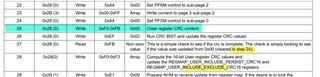
This is referenced in SLVAF93A

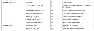
and from SLVUCD4 i can assume this is GENERAL_REG_1 ?


These are not even listen in Scalable PMICs GUI
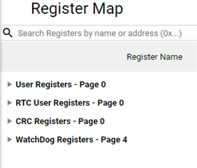

Really fustrating

  • Hello Kimmo,

    Page 1 of the register map is not available to the public. It contains many internal only registers. 

    In regards to the REG_CRC_EN bit, for a released NVM the default value should be listed in the corresponding user guide. Just as it is in SLVUCD4. Please let me know if this is not the case for a particular NVM.

  • Yes, it is enabled by default for this part.

    Intention is to clear REG_CRC_EN bit for first NVM programming tests. I need to change just couple of bits to get the board powered up, (the actual programming tool will be developed later)

    As it can not be disabled from the GUI, so i need to modify it by hand and it was first bit to look from the documentation - ended up in this undocumented rabbit hole.

    Also 0x22 and 0x23 are mentioned in SLVAF93A table D-1, but no acutal explanation given

    So only way to figure out page 1 bits is by reverse engineering, change them 1-by-1 from the assembly listing and compare the binary output?

    e.g. EN_OVP is page1 register 0x17 bit 0

    You really should document and publish (at least) these registers which are mentioned in the documentation.

  • And now i managed to brick the PMIC... all I2C register reads are 0x00

    Following the table D-1 in SLVAF93A is not too easy. I just want to disable the REG_CRC_EN

  • My device is TPS65941515

    Lets forget the REG_CRC_EN

    Can provide example listing what i need to do, if i want just to change the VCCA limits to 5V (0x2C bit 6 VCCA_PG_SET to 1) and CUSTOMER_NVM_ID to 0x81 (to identify it is programmed) ?

    The part is powered from 3.3V (VCCA and VIO) during programming, and will be powered from 5V during normal operation.

    Enable pin is held low until there is 5V in VCCA

  • Ok, Seems i managed to set the VCCA_PG_SET=1 thus placing the VCCA in undervoltage situation (as it is now 3.3V) and I2C returns all zeros... doh
    Applying 5V to VCCA and i can see the register values again.

  • Hello Kimmo,

    Try using this .json file in the Revision 3 of the GUI. This should make it easier to do a custom NVM similar to the TPS65941515 and program it onto an EVM.

    https://e2e.ti.com/cfs-file/__key/communityserver-discussions-components-files/196/TPS65941515_5F00_.json

  • I have this json, but using json is not an option as i do not have anything to parse it or program the device with it.

    I have also the "binary" output from the GUI, which is also a bit useless in my case. At least i have not found any example code to utilize it.

    But i think we can close this question now, but please, consider updating the documentation with the register maps for these registers that are needed when programming the PMIC (in table format)

    Also there is some typos in table D-1 (SLVAF93A)

    Should be step 25 and EXCLUDE_PERSIST (?)