


Hello,
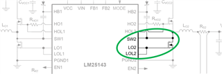
my question is on the max rating of SW1/2 of LM25143-Q1. Currently they are specified with -0.3V.
Wouldn't this be an issue, in case LOL1/2 gets open?
Thanks and best regards,
Michael
Hello,
my question is on the max rating of SW1/2 of LM25143-Q1. Currently they are specified with -0.3V.
Wouldn't this be an issue, in case LOL1/2 gets open?
Thanks and best regards,
Michael


