This thread has been locked.

If you have a related question, please click the "Ask a related question" button in the top right corner. The newly created question will be automatically linked to this question.

TPS6521905: power down timing

Part Number: TPS6521905
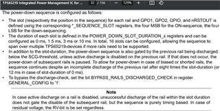
Other Parts Discussed in Thread: TPS65219

Hi,

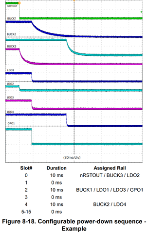
Could you explain below difference between register input and actual results in the datasheet figure8-18?

In below picture, nRSTOUT/BUCK3/LDO2 power down at same time is programmed and it works well.

After 10ms, BUCK1/LDO1/LDO3 power-down is programmed but in the picture, it is around 18ms.

After 10ms, BUCK2.LDO4 power-down is programmed but in the picture, it is around 50ms.

Please let me know how power-down timing is measured.

Thanks.

  • Hi,

    Thanks for reaching out. The power-down sequence of the TPS65219 PMIC is gated by the following two items: slot duration and rails discharged below the SCG threshold (~260mV). 

    The power-down sequence in the scope capture from your previous message shows that nRSTOUT/Buck3/LDO2 are turned OFF first but, after 10ms (slot duration) the output voltage on Buck3 is still above the SCG threshold (~260mV). Once Buck3 is discharged below the SCG threshold, the PMIC continues to the next power-down slot in sequence.

    This PMIC feature that waits for the rails to be discharged below the SCG threshold can be disabled by changing the "BYPASS_RAILS_DISCHARGED_CHECK" register field before the power-down sequence is executed.   

    Thanks,

    Brenda