This thread has been locked.

If you have a related question, please click the "Ask a related question" button in the top right corner. The newly created question will be automatically linked to this question.

TPS25750: How to switch power role from Sink to Source and vice versa

Part Number: TPS25750
Other Parts Discussed in Thread: BQ25731, , TPS25751, TPS25751EVM

Hello,

we use TPS25750 with BQ25731 both controlled over I2C from microcontroller. We use 4s battery connected to BQ25731

We configured TPS25750 Application Customization Tool in the following way

1. first picture power source and power sing with TPS25750D with BQ connected
2. maximum power sourced 100W
3. maximum power sink 100W
4. preferred power role Sink
5. No USB data is being used

in advanced configuration we set up

Transmit sink capabilities 4 PDOs
1. PDO1 - 3A 5V
2. PDO2 - 3A 9V
3. PDO3 - 3A 15V
4. PDO4 - 3.25A 20V

Transmit source capabilities 1 PDO
1. PDO1 - 3A 5V

Now when we connect wall adapter PD source capable of 5V 3A, 9V 3A, 15V 3A, 20V 3.25A. Sink TPS25750 communicates with source and they establish PD connection using 20V 3.25A. Battery charging can start.

When PD source is removed, system stay powered up from battery. When we connect PD Sink (mobile phone) nothing happens, i would expect TPS25750 to switch its role to PD Source and establish PD contract with Sink using 3A 5V PDO1 available.

Do you have some guidance on which steps should be performed to switch from Sink to Source (and in consequence then back from Source to Sink) as I cannot figure it out from the documentation.

Thank you

  • Hello,

    Based on what you have described in your setup, everything should be working correctly, but I want to confirm that you have a proper configuration before we continue.

    Please export the JSON file from the GUI and attach it to this thread so that I can confirm that you are setup correctly, if you don't know how, I can help with the process.

    Do you have a PD analyzer that we can use to see what is happening on the PD bus during the second connection?

    Here

    Also while you wait for my response, please try to connect a battery that is charged and the connect the phone first before starting as a sink to see if you get a source PDO.

    Regards,

    Chuck

  • Hello,

    the JSON file is here:

    {"questionnaire":{"version":"7.0.4.7","answers":[0,4,4,1,0,null,1,null,1,null,2,16.8,4.096,null,null],"options":{},"configID":"0000","vendorID":"0000"},"configuration":{"data":{"selected_ace":[{"register":6,"data":[0,0,0,0,0,0,0,0]},{"register":22,"data":[10,48,48,77,0,0,0,0,0,0,3]},{"register":50,"data":[1,168,42,44,145,1,38,44,209,2,0,44,177,4,0,244,65,6,0,0,0,0,0,0,0,0,0,0,0,0,0]},{"register":51,"data":[4,44,145,1,16,44,209,2,0,44,177,4,0,244,65,6,0,69,65,6,0,0,0,0,0,0,0,0,0]},{"register":92,"data":[48,0,0,0,0,0,0,0,0,16,0,0,0,0,0,0,48,0,0,0,0,0,0,0,0,12,0,0,0,0,0,0,0,0,0,0,0,0,0,0,0,0,0,0,0,0,0,0,0]},{"register":117,"data":[0,0,0,0]}]}}}

    - could you recommend me some particular PD analyzer which I should use please? We don't have one, we have only oscilloscope with basic spectral analyzer

    - I suspect, that mobile phone connects as source as it powers up our HW with 5V

    - We have ST development board which contains USBC PD Sink device with USART interface and if I connect our HW without battery to it it keeps writing again and again.
    *** [0] attached on CC2 (Source)
    *** [0] detached
    *** [0] attached on CC2 (Source)
    *** [0] detached
    *** [0] attached on CC2 (Source)
    *** [0] detached

    - Also with ST dev board - If I connect our HW with battery it writes the states bellow again and again. Maybe this can help...
    *** [0] attached on CC1 (Sink)
    *** [0] selected cap #1
    *** [0] PS Ready received
    *** [0] PRS new role: Source
    *** [0] detached
    *** [0] attached on CC1 (Sink)
    *** [0] selected cap #1
    *** [0] PS Ready received
    *** [0] PRS new role: Source
    *** [0] detached
    *** [0] attached on CC1 (Sink)
    *** [0] selected cap #1
    *** [0] PS Ready received
    *** [0] PRS new role: Source
    *** [0] detached

    thank you

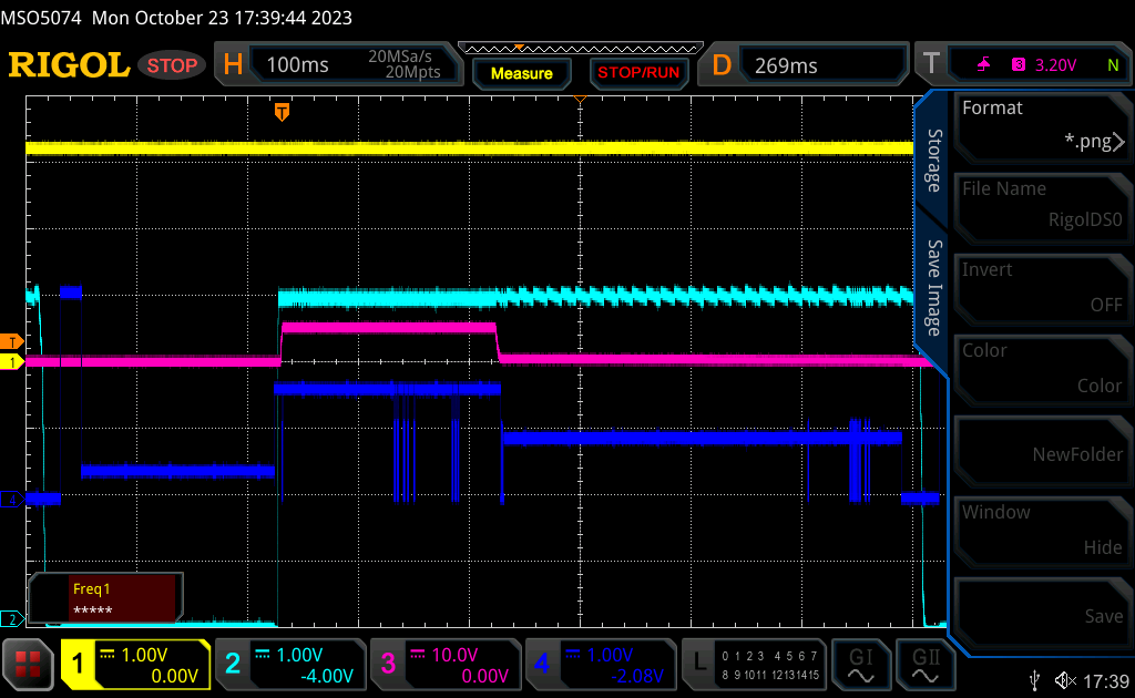
  • Here is what it is behaving connected to ST dev board.

    CH1 - I2C clk
    CH2 - CC1
    CH3 - VBUS
    CH4 - CC2

  • Jan,

    I am going to out of the office unexpectedly this week, so I will be transferring support on this to someone else after this message.

    One of the better PD analyzers available is from Lectroy:  https://www.teledynelecroy.com/protocolanalyzer/usb/mercury-t2c-t2p

    A more budget friendly option is the USB-EZ-PD that Infineon sells.

    What I am seeing in you logs is that for some reason, the phone is initiating a power role swap where the TPS25750 is being changed from a source to a sink and that is consistent with what you are seeing.

    Can you please provide scope captures of the I2CM bus, PP5V, and PPHV into the TPS25750?  It looks like the system is trying to do a power role swap and the TPS25750 is detecting a failure in voltage and disconnecting.  This may be caused by a communication issue with the  BQ25731 and we will need to see what is happening on the communication and input side.

    Regards,

    Chuck

  • Thank you for PD analyzers recommendations, the one from infineon is this one? www.infineon.com/.../

    We don't have connected I2Cm bus of TPS25750, we have both I2C of TPS25750 (I2Cs) and BQ25731 (I2C) connected to microcontroller.

    We have at this step enabled only one Transmit source capabilities 1 PDO - 1. PDO1 - 3A 5V in order to not to have to set up BQ25731 in any way. 5V 3A are supplied by DC/DC converter from VSYS (battery).

    Do you still need all I2CM bus, PP5V, and PPHV scopes?

    I hope we will be able to add more Transmit source capabilities PDO e.g. 9V 3A, 15V 3A, 20V 5V later and be able to enable them manually by sending commands to BQ25731 from microcontroler.

    Thank you

  • Hi Jan,

    The device expert is currently out of the office. They will look into this and provide a response when they return. Please expect a delay in their response accordingly.

    Thanks,
    Field

  • Hello,

    ok, no problem, I will wait.

    In meantime I was playing with TPS25750 Application Customization Tool and when I checked "USB Suspend Supported" it started to behave correctly. Mobile phone begins to charge and connects as Sink (our HW as Source) and also ST development connects as Sink with our HW (source).

    So now the question is, ho can I synchronize with BQ25731 settings? I add more than 1 PDO Source capabilities and PDOs with voltage higher than 5V has to be powered through PPHV from BQ25731, right?

     I mean, when should I send OTG configuration to BQ25731 during PD contract establishment? As I wrote earlier, we communicate with BQ25731 from mcu, not over I2Cm from TPS25750.

    Is there some way of e.g. configuring some TPS25750 GPIO to signalize it is the time to turn on BQ25731 OTG voltage on PPHV, or how can I recognize it is the time to do so?

    thank you

  • Unfortunately I experience the same problem as on the beginning when I add more than 2 PDOs under "Transmit Source Capabilities" in TPS25750 Application Customization Tool. E.g. PDO1 5V 3A, PDO2 9V 3A, PDO3 15V 3A. It is weird

    Thank you

  • OK, when I set "preferred power role" in TPS25750 Application Customization Tool then it is working again regardless of Transmit Source Capabilities PDO1 USB Suspend Supported settings

  • Hello,

    we proceeded to next step and started to enable OTG/VAP/FRS pin of BQ25731 driven by TPS25750 GPIO EnableSource 73code. All in Source mode.

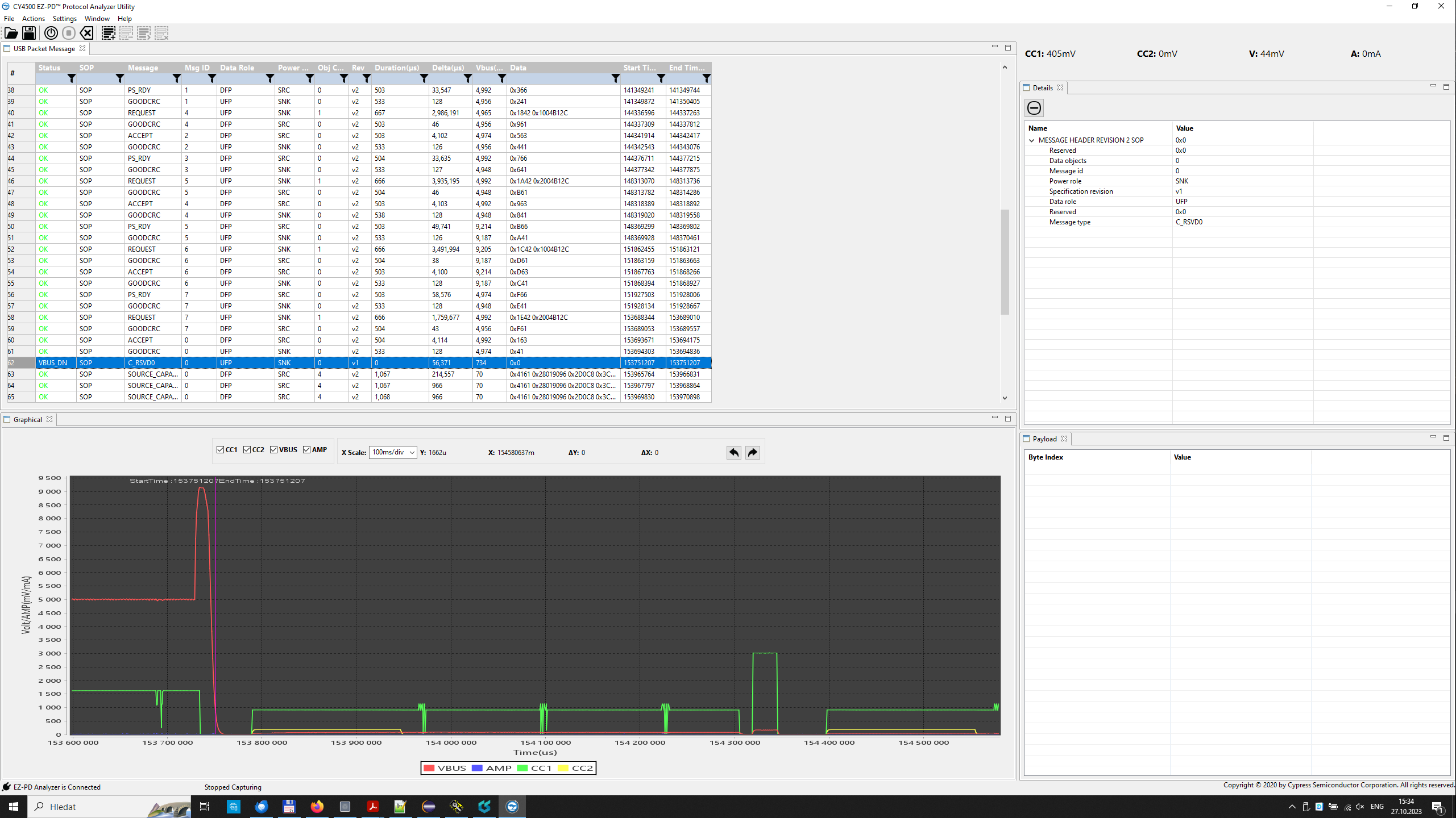
    At first place we enable OTG output of 9V 3A permanently and try to switch between 5V 3A (cap1) and 9V 3A (cap2) using our ST development board which allows to send Power Source requests to USBC PD Source device.

    We can toggle between modes successfully couple of times, but then we always encounter problem, that VBUS drops to zero after short time after switching to 9V.

    I attach screenshot from USBC PD analyzer from infineon you recommended us.

    Do you have any tips on what is happening?

    Also I noticed through PD analyzer, that setting of Unchunked Extended Message Support + USB Communication Capable + USB Suspend Supported in TPS25750 Application Customization Tool makes no effect as it is always transferred as false + true + true (checked in PD analyzer output)

    Thank you

  • Hi Jan,

    Sorry for the delays on response. Chuck should be back early next week to support your questions.

    Thanks and Regards,

    Chris

  • Hi Jan,

    I am just back in the office today, but I do not have time to look at this until tomorrow.

    Regards,

    Chuck

  • Hi Jan,

    This is similar to another issue that we are working on with another customer.    We will get back to you later this week with a resolution.

  • Hi Chuck,

    do you have any good news with problem solution progress please? thank you

  • Jan,

    We have a potential solution that our team is testing in our lab now.  I will update you tomorrow once they complete the testing

  • Jan,

    The current fix was not completely robust.  We have a pin for pin compatible part that will be releasing soon that does address this issue.  Do you have access to a TI FAE?

    Regards,

    Chuck

  • Hello Chuck,

    what does it mean soon? This product is very urgent one and we have to release it at the end of November.

    Can I ask you, how it is even possible, you offer this product as a active part, recommended for new designs, while is not completely tested?

    We do not have access to TI FAE. Should we sign in?

    Thank you and kind regards,

    Jan

  • Hi Jan, 

    Apologies for the difficulty here and appreciate your patience as our team has worked to try and resolve these issues. As Chuck mentioned in the previous post, we have been working on releasing a new follow on device to the TPS25750, the TPS25751. An initial version of this device will be available within the next month, and we are planning to fully release it to market in 2024. 

    The TPS25751 address this issue, as well as includes other next generation features such as liquid detection and PPS. Unfortunately, with the team focusing on releasing this new device, we will not be pulling in fixes to the TPS25750 that will be addressed in the TPS25751. The TPS25751 will be pin to pin compatible with the TPS25750, so migration to the new device should be straightforward. Apologies for the confusion and the difficulties this may pose. 

  • Hello Adam,

    we appreciate your honest response. We are glad we know, we don't do anything wrong.

    Anyway, our FW engineers spent on that tens of hours trying everything. No success, after that, we contacted you support. So I am sure you know, how expensive and exhausting it was for us and will be, because we cannot sell the products next months.

    I am very shocked, that part, which is selling for more than 3 years, is not functional and there is no warning on your web "not recommended for new designs" or something like that or ERRATA notes, which would describe this behaviour. Function we need is a basic function, which you declare, this part can do and everybody, who wants to use TPS25750 for acting as a source!

    We are quite desperate from a fact, you are not going to support current part TPS25750 and we should be waiting for next TPS25751. We cannot finish development or make HW till you announce the new part TPS25751.

    I would like to ask you:

    1) If it is possible to send us TPS25751 next month to test these functions?
    2) Will be part compatible with current SW design tools? Will be available datasheets as well next month?
    3) Which month of year 2024 do you expect will be TPS25751 ready to be ordered and delivered?

    I understand, how important for us are answers on questions above and thank you for honest answers.

    Kindly use our email info@betso.eu if these informations are not public now.

    Thank you and kind regards,

    Jan Zastera

  • Hi Jan, 

    Understand your frustrations and once again I apologize for the difficulty this has caused you. Let me work with the team to get you responses to your questions and share some additional information, I will get back to you before the end of the week. 

  • Hello Adam,

    do you have any news for us, please?

    Thank you

  • Hi Jan,

    Unfortunately we cannot send any information on this device before its release on TI.com. We are about to start the signoff process for release of this device, so should have something on the web within the next month. Once it releases on TI.com, there will be the full datasheet, EVM, GUI, and user's guide. There will be a new GUI tool, but it implements the same check box approach as the TPS25750 so transitioning to the new device and GUI should be straightforward. 

  • Hello Adam,

    Regarding TPS25750 we found another weird behavior, when connected as PD Source (TPS25750) to PD Sink (ST development board) at 5V the PD contract is lost after couple of minutes, is this also a known behavior and will it be repaired in TPS25751, please?

    Next, we were able to order TPS25751D samples from ti.com page and already received the samples. Do you know when will be GUI Application customization tool available? Or is it fully compatible with GUI Application customization tool for TPS25750?

    Thank you and have a nice weekend

  • There are a couple of known behaviors with the TPS25750 that this could be a result from. 

    There is actually a new GUI. We are working on getting that added to the main page, but you can find a link to this new GUI in the user guide for the TPS25751EVM. This user guide also talks through how to use the GUI. Is very similar to the TPS25750 GUI. 

    https://www.ti.com/tool/TPS25751EVM