This thread has been locked.

If you have a related question, please click the "Ask a related question" button in the top right corner. The newly created question will be automatically linked to this question.

BQ25886: Device cannot pass poor source qualification

Part Number: BQ25886

Hello Sir:

We are using BQ25886 and test poor source qualification.

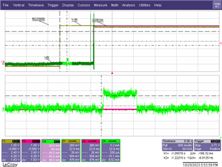
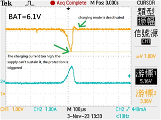
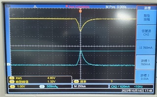
But when battery voltage is under 3.8V and input source is 5V/0.5A.

The input voltage will drop and under to 3.8V, and input current sink around 700~800mA. 

When this moment BQ25886 cannot enter charging stage and STAT pin is blinking.

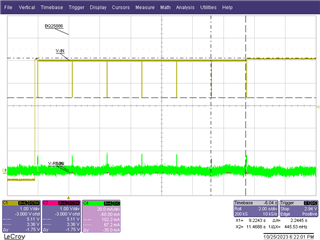
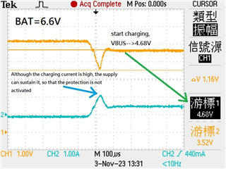
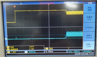
When battery voltage is over 3.8V, that input voltage and current waveform will become below figure.

When this moment BQ25886 enter charging stage normally.

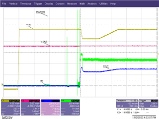
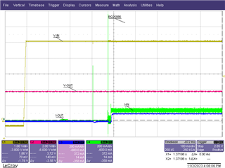
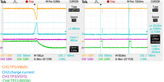
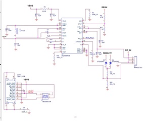
Our schematic shows below, in this testing VSYS has no load.

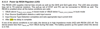
Please let us know why the sink current is over 30mA (Ipoorsrc typ is 30mA in datasheet)?

How to improve the poor source qualification pass rated?

Looking forward your feedback.

Thanks a lot.

  • Hello

    We have reviewed the schematic and have a couple of recommendations:

    1.) BTST pin -- C4 is 10uF, this is a little large recommend value 47nF.  This could cause problems at start up.

    2.) SYS pin -- C5 is 10uF, recommended value is 2 X 22uF, better value to use.

    3.) REGN pin -- C6 is 10uF, recommended value is 4.7uF.

  • Hi Bill:

    Sorry, we follow your recommend to do, but which is no use on this issue.

    We still has below questions.

    Looking forward your feedback.

    Thanks a lot.


    1. When testing Poor Source Qualification, why is the input current load higher than 15~30mA? The load draw at the moment of measurement can reach 750mA.

    2. When testing Poor Source Qualification, why is the input current load not controlled by ILIM? Our circuit is set to 500mA, why does the load reach 750mA?

    3. When testing Poor Source Qualification, why is the input current load related to the battery SOC?

    4. When testing Poor Source Qualification, why does the input current load not reach 750mA when the battery voltage is high?

    5. Can you try it on EVM and update your tested results for us? Just find an older PC and use their USB port, we found that IPOORSRC load is significantly higher than 15~30mA. 

    6. Is there a way to skip Poor Source Qualification? Or how to increase the chance of success of Poor Source Qualification?

  • Hi

    Working on this in the lab will try to have update to you COB Oct 25 Dallas time

  • Hi

    Couple of things to check:

    1.) Poor Source should be a 30ms pulse about 160mS after VBUS is applied, current will be about 15mA.

    2.) Check the REGN voltage, if you have a Poor Source fail it will not turn on.

    3.) Also the Poor Source will try 7 time at 2 sec intervals then shutdown, (HIZ Mode)

    Scope Capture of normal start up and zoom in on Poor Source Pulse.

    Scope Capture of fault condition, 7 pulses then shutdown.

  • Hi Bill:

    Please refer this video, we found a poor source and used EVM on these source.

    We found that EVM had blinking the LEDs, this behavior liked our issues. 

    Would you please let us know what points you want to check?

    Please kindly provide a list for us, we want to step by step fixing this issue.

    Looking forward your feedback.

    Thanks a lot.

  • Hello,

    Can you try to use a power supply that is rated for 5 V 3 A and see if you can charge?

    Regards,

    Mike Emanuel

  • Hi Michael:

    Of course use 5V/3A that EVM will be working normally.

    But the question is we can not pass the poor source qualification processing when using 5V/0.5A source on EVM or our product.

    We need to know your tested results when using 5V/0.5A source. 

    Scope Capture of normal start up and zoom in on Poor Source Pulse.

    Does this figure working on 5V/0.5A source?

    Looking forward your feedback.

    Thanks a lot.

  • HI 

    With 5V / 0.5A source we do not see the STAT blinking led stage, see below start up with 7.2V BAT simulator.

    With Reduced battery voltage, 3.8V it is similar:

  • Hi Bill,

    According to your experimental results, your VBUS voltage did not show significant drop under current load. This is an ideal power supply. However, the user’s USB interface cannot provide power enough, which will result in the outcome shown in the attached image.

    Pic2 shows that when the charging current is too high, the supply cannot sustain it, and the IC’s protection or reset mechanism is triggered.

    Do you have any ideas for a workaround?

    Thanks

  • Trying to duplicate your test set up.

    Is the scope capture with customer adapter or power supply?

    Checking your test condition on the BQ25886:

    UPDATE --Any jumpers different from factory setting?---I used jumper settings from video for additional test.

  • Hello

    I suspect the device may be going into UVLO at 3.3V and resetting.  Can you show a wider scope capture that shows when the input voltage dip happens, how long after power is applied?

  • Hi Bill,

    Left-side pic is single trigger and right-side pic is continuously capture,

    we notice the period is 220ms.

    The battery has an ultra-low internal resistance of 100mΩ.

    This means that if the IC turns on the MOSFET for too long and does not get a quick response by the current sense,

    the VBUS may not sustain the power consumption, so it starts to drop. This may not be seen by the battery emulator

  • Hi John

    I am testing with lower input voltage and have duplicated the 200ms pulsing condition customer is seeing. Trying to understand the problem a little better and looking for possible solution.

    Does the customer have option to use higher current adapter?

  • Thank you for your efforts. Replacing the adapter with a stronger current can eliminate this phenomenon. However, it may not be the best solution as it could lead to a loss of users on the computer side. In that case, simultaneous charging and transmission via USB is an attractive feature

  • Hi John

    Can you test with a 33uF or 47uF capacitor on the V-BUS?

    This is working on my tests in the lab.  Will reduce Bus voltage drop. This may not be practical solution but more of a test.

  • Hi Bill,

    Thanks for your suggestion. Would enlarging the capacitor to over 100uF affect the poor source qualification?

  • Hi John

    Yes 100uF should work also.

    I have been looking at how to prevent the overload and voltage dip that is causing the problem -- but have not had any luck at this point.