This thread has been locked.

If you have a related question, please click the "Ask a related question" button in the top right corner. The newly created question will be automatically linked to this question.

TPS2121: PR1 Fluctuation

Part Number: TPS2121

Hello,

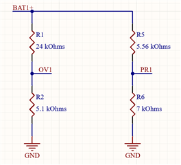
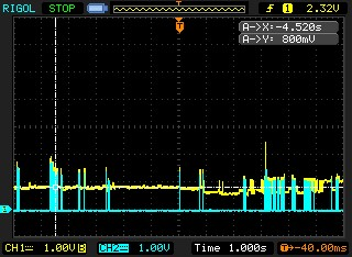
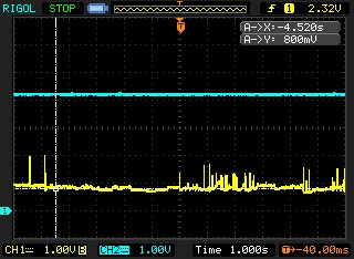
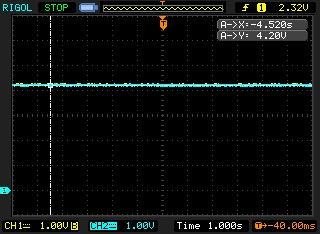
Does anyone have an idea as to why the PR1 signal on my prototype PCB is fluctuating as shown in the oscilloscope image below? This is happening on many samples, but not all. I've also included the schematic portion showing the voltage divider. My hysteresis resistor is set to 71.5 kOhm.

  • Hi GP,

    What is the IN1 typical voltage?

    Can you send a waveform with this issue that shows IN1, PR1, OUT, and ST?

    Thanks,

    Patrick

  • Hi Patrick,

    Unfortunately, my scope is only 2-channel, so I had to take the captures separately. 

    Image 1: blue is ST and yellow is PR1.

    Image 2: blue is input 1 and yellow is PR1.

    Image 3: blue is input 1 and yellow is output (exactly overlapping).

  • Hi GP,

    It looks like the device is frequently switching between IN1 and IN2. Perhaps the PR1 and CP2 steady state values are very close to each other? Can you send the CP2 side of the schematic too - and I am guessing that BAT1+ = BAT2+ = 4.2V?

    My other instinct is that it could be a soldering issue, but that is ruled out as you mentioned that this takes place on numerous boards. I calculate that with VBAT1+ = 4.2V, PR1 should be at 2.34V, but it looks to be less than 1V while IN1 is active.

    Thanks,

    Patrick