A related question is a question created from another question. When the related question is created, it will be automatically linked to the original question.
If you have a related question, please click the "Ask a related question" button in the top right corner. The newly created question will be automatically linked to this question.
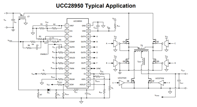
The EA + is the non inverting input to the error amplifier. The output of the error amplifier controls duty cycle.
If EA + is greater than EA - the output of the amplifier will go high demanding more duty cycle. If EA - is greater than EA + the output of the error amplifier will go low demanding less duty cycle.
hello mike o, thanks for knowlege sharing but i have one more doubt, like this EA+ Greater than EA- the output of the amplifier will go high demanding more duty cycle that is ok, but my doubt is how controlling constant current & constant voltage the output DC
The UCC28950 can be directly setup for peak current mode control of peak voltage mode control. The device does not come with all the circuitry necessary for constant current/constant voltage mode control.
If your require constant current/constant voltage mode control more than likely you are designing a battery charger.
The following link will bring you to 2 kW phase shifted full bridge battery charger reference design using constant current/constant voltage mode control.
The following link will bring you to an application brief written by the engineer that did the 2 kW design. I believe you will find the reference design and application note helpful in your design process.
Ucc28950 EA+ feeding voltage 1v but dutycycle increase 50%, we measured different dutycycle that times works but now not working properly, what's the problem in controller?
The EA + is typically used to set the DC control voltage as shown below. The internal voltage amplifier will raise or lower the comp pin until the correct output voltage and duty cycle is achieved. If EA - is < EA +, COMP will increase to increase duty cycle and the voltage at EA -. If EA - is > EA +, COMP will decrease to decrease the duty cycle and the voltage at EA -.
So if your duty cycle is increasing that would indicate that VOUT is low and the controller is trying to achieve the desired output voltage.