This thread has been locked.

If you have a related question, please click the "Ask a related question" button in the top right corner. The newly created question will be automatically linked to this question.

LM25145: LM25145 - MOSFET Power Loss calculation - WEBBENCH or splr001a.zip

Part Number: LM25145
Other Parts Discussed in Thread: SYNC-BUCK-FET-LOSS-CALC, CSD18531Q5A

Dear TI Team,

I try to find the best fitting MOSFET's for my design, as we have currently temperature issues during bringup.
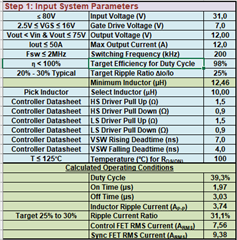
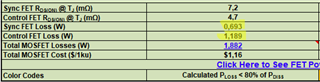
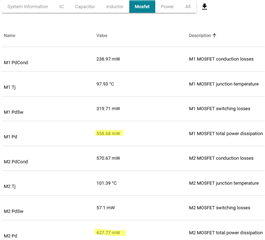
I tried the WEBBENCH and also the Tool "splr001a.zip" (SYNC-BUCK-FET-LOSS-CALC_Rev2.xlsm).

Unfortunately I get quite different results for the Powerloss for both MOSFET's with WEBBENCH or splr001a.zip.

Could you please tell me which of the tools I should trust for the power dissipation calculation?

Thank you very much for your support!

  • Bernd,

    What is the scale of the difference you are seeing? What FETs are you using and what are your design specs?

    Many power losses are easy to calculate but there are some that are non-trivial to model mathematically, for example QRR losses which are determined by low-side QRR but cause losses on both low-side FET and high-side FET, due to slowing down SW transition time.

    Both tools should give similar enough results, and only be off by a few % of total efficiency.

    Let me know,

    -Orland

  • Orlando,

    Thank you very much for your fast support!

    My design parameters are:

    Input Voltage 15-31V due to undervoltage lockout (Normally only 16-31V)
    Output Voltage 12V @ nominal 10A (due to RDS-ON Over current protection and it's deviation on input voltage we now calculate with 12A)
    Operating Temperature Range 0-70°C

    Attached is the current design we need to optimize concerning Power losses => lower temperatures: Used Top+BOTTOM MOSFET's: TI CSD18531Q5A
    Inductor: VISHAY IHLP5050FDER4R7M51 Datasheet: IHLP5050FDER4R7M51

    Do you see issues in assembling Q5B packages on a Q5A footprint for testing purposes? (especially for thermal performance) 

    The deviations we see in both tools are the following:
    Parameters: 
    Top/M1/ControlFET: CSD18540Q5B

    Bottom/M2/SyncFET: CSD18513Q5A

    SYNC-BUCK-FET-LOSS-CALC_Rev2.xlsm:

    WEBENCH:

    8308.DMS-LS09_A101_Power_Board_EVT_Schematic_0.04_20230809_TI_Check.pdf


  • Bernd,

    Based on the MOSFET temperatures, I suspect one of the tools might be adjusting RDSON based on a FET temperature coefficient, at higher temperatures the FET RDSON increases, and this will increase conduction losses. 

    The SYNC BUCK calculations mentions conduction losses for RDS@Tj, so that my be why the excel tool gives higher losses, especially on low-side MOSFET where conduction losses are more dominant.

    Hope this helps,

    -Orlando