This thread has been locked.

If you have a related question, please click the "
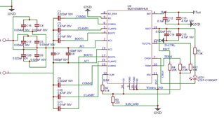
Ask a related question" button in the top right corner. The newly created question will be automatically linked to this question.

BQ51050B: Charge complete is not shown by transmitter when BQ51050B is used as reciever

Part Number: BQ51050B

We are using this for our wireless charging receiver. We are able to charge but unable to get the fully charged info on the transmitter. For a brief moment it shows that it is fully charged but immediately goes into charging mode. this happens continuously. We have connected TS/CTRL pin to GND with 10K res making the function unusable. We are charging a 3.7V li-ion single cell battery. Can you have a look and let us know if this is the issue and can be resolved by pulling high the TS/CTRL pin to Vbat with 10K res? if so, how can we stop it at 4.2V

  • Hello

    The BQ51050B will send EPT01 charge complete to the TX when current falls below Termination value.  The transmitter shutdown as you see but when it checks when the RX it needs to charge again.  This is probably what you are seeing.  It will vary from transmitter manufacture to manufacture.

  •  this is the transmitter we are using for charging and it will be the final one. But how to have a constant EPT saying battery has reached to a certain voltage for the end user?

  • Need to check on this in lab, will get you an update tomorrow.

  • Thank you, Iooking forward for the update

  • Hello

    A couple of things to look at:

    1.) The BQ51050B will set charge complete when voltage reaches 4.2V and current drops below value set by the TERM / ILIM pin.  At that point it will send EPT01 to TX and continue until the battery voltage drops 100mV.

    2.) If the AD pin is pulled above 3.6V RX will send EPT00 to TX and can be restarted releasing the pin, pull to gnd.

    For a brief moment it shows that it is fully charged but immediately goes into charging mode.

    What is the battery voltage doing when this happens?  Should reach 4.2V and hold at that point, is a load on battery?  When the voltage drops 100mV it will restart charge, release EPT01.

  • battery voltage when that happens is 4.185V when I tested with multimeter SO it should be accurately 4.2V with 0 tolerance? 

    What you mean second one pulling up AD pin sends EPT00 means accepting power and restarting by releasing the pin means not accepting power anymore? You mean using external controller on this?

  • battery voltage when that happens is 4.185V when I tested with multimeter SO it should be accurately 4.2V with 0 tolerance? 

    This looks right, range is 4.16V to 4.22V.  This would be the charge complete voltage and recharge would be 100mV decrease from this point.

    What you mean second one pulling up AD pin sends EPT00 means accepting power and restarting by releasing the pin means not accepting power anymore? You mean using external controller on this?

    Yes if you have an MCU that could enable or disable charge then controlling the AD may be an option.

  • Hello Bill, we bought EVM for this IC  to test the AD pin. 

    When I apply voltage of 3.6V+, the IC is getting powered off or is not taking any voltage. 

    there is a line in the datasheet of EVM

    "5.2.1 J1 – AD External Adapter Input, J2-GND Power can not be provided to simulate an external adapter applied to the receiver in this bq51050BEVM764 (HPA764-002)."

    It means we cannot test accurately but if we implement it on the board and send in voltage of 3.6V+ it deactivates IC

  • Hi 

    Yes, the IC will turn off the transmitter when AD is pull high (3.6V), also for charge complete.

    For your Test Condition what behavior do you need from the Receiver and Transmitter?

  • So for our condition we want the IC to say to transmitter that charge has completed. Either by pulling AD high or normal communication. 

    When I tested using the devkit, it turns off the IC but the transmitter LED's charging and charge complete LED blink one after the other continuously 

  • Hello

    The BQ51050B will automatically detect the charge complete and turn off transmitter. Are you seeing problems with this feature?

    The BQ51050B will set charge complete when voltage reaches 4.2V and current drops below value set by the TERM / ILIM pin.  At that point it will send EPT01 to TX and continue until the battery voltage drops 100mV.

  • Yes, you can have a look at our circuit. it doesn't detect automatically .we are trying to make AD pin accessible to MCU and turn it off

  • Hello 

    Charge Complete Question:

    Circuit looks OK do not see any problem that would prevent charge complete.  Charge current is 588mA with termination at 10% or 58mA.

    Something to Check if you have a load on the OUT it could delay or prevent termination, current will not fall below 58mA as expected.

    Transmitter:

    When transmitter receives charge complete message (EPT01) it will remove power from receiver.  When it reapplies power to receiver to check status is TBD.  Some manufactures of transmitters do not power receiver again, the receiver has to be removed and placed back on transmitter.  The TI devices will power receiver every 500ms.

    Receiver behavior during charge complete:

    1.) Current falls below termination set by TERM resistor and Receiver sends EPT01 to transmitter.

    2.) When transmitter tries to power the receiver and battery is above 4.2V -110mV first packet the receiver sends is EPT01 again.

  • How is charge current 588mA, I wanted to have a charge current of 1A. According to the datasheet I have calculated resistors to be Rilim as 314ohm and termination would be at 100mA. Rterm in the calculation was 2.4k. how else it needs to be calculaed? 

  • The Charge Current value is set by R2 (314 ) + R3 (220). The FOD resistor is part of the charge current calculation.

  • So, if RILIM is 534 then we will have a current of 1A for charging. so, 10% of it would be 100mA and termination happens when current falls below this right? 

    can you also let us know if other values of resistor and capacitor are correct. We are going into mass production next week and would like to rectify all

  • For 1A output current the total value for R1+RFOD (R2+R3) will need to be 314.  Keep R3 = 220 and change R2 to 100, this will total 320.

    The K-ILIM value is 314.

    With R2+R3 = 320 the 314/320 would give you 980mA.