Because of the holidays, TI E2E™ design support forum responses will be delayed from Dec. 25 through Jan. 2. Thank you for your patience.

This thread has been locked.

If you have a related question, please click the "Ask a related question" button in the top right corner. The newly created question will be automatically linked to this question.

BQ25570EVM-206: Connecting RF harvesting circuit to BQ25570 EVM

Part Number: BQ25570EVM-206
Other Parts Discussed in Thread: BQ25570

Hello,

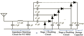
I have purchased BQ25570 EVM to use as a power booster for RF energy harvesting. I am connecting a RF energy harvesting circuit to BQ25570 EVM and looking at the VSTOR output. The RF circuit is a voltage doubling circuit with 22 stages followed by a storage capacitor. 

The issue that I am facing here is that without connecting the BQ25570 EVM, the voltage at the storage capacitor of harvesting circuit goes up to 4V.. But as soon I connect the circuit to BQ25570 EVM, I see that the voltage drops drastically to 300mV at the storage capacitor. I am assuming that there is some kind of load effect that is happening due to which there is drop in voltage. I am not sure reduce this load effect.

I have attached the circuit diagram of my energy harvesting circuit. Any helpful answers are appreciated.

Thank you
  • Hi Yoganand,

    When the BQ25570 is connected to your energy harvesting circuit it will pull current to charge both the VSTOR capacitor and the storage element. The VSTOR capacitor is also connected to the integrated Buck as well which may be pulling current.

    What is the expected current output of your energy harvesting circuit and how large is your storage capacitor? If it is a small storage capacitor its likely that the start of boost operation, pulling current to charge the inductor, is draining the storage capacitor.

    Best Regards,

    Juan Ospina

  • Thanks for reply. The storage capacitor that I am using is 10uF and the expected current output is in the range of 170uA - 200uA, 

  • Hi Yoganand,

    I believe the storage capacitor you are using may be too small. It's likely that when the energy harvester quickly charges the boost inductor it is draining your storage capacitor. The energy harvester will attempt to pull about 200 mA until the storage element falls below the MPPT point, but that might be sufficient to discharge your storage capacitor.

    Can you share a waveform of your input voltage as well as VSTOR and LBST when the energy harvester is powered up?

    Best Regards,

    Juan Ospina

  • Is it 200uA or 200mA? 200mA is a lot of current to get out of such energy harvesting circuits. Yes I will try to share the waveforms. However, I don't think the harvester is exiting the cold start mode.

  • Hi Yoganand,

    This is 200 mA that it will attempt to pull. 

    Best Regards,

    Juan Ospina

  • Thanks for your clarification, Juan. I have couple of follow-up questions:

    • I don't think my circuit will be able to provide 200mA of current. Is this current consumption because of the evaluation board or BQ25570 by itself requires that much current?
    • Currently, in the evaluation board, I have set the MPPT point to 50%. Instead, using resistors (R_OC1 & R_OC2) to set the reference voltage to a lower value (100's mV) will reduce the current?

    Thank you very much for your timely responses and sorry for asking too many questions.

  • This is current that the device itself requires in order to charge the boost inductor in order to conduct switching action. The device will stop pulling current from the input source when the input source voltage drops below the MPPT value, so raising the MPPT point may improve the performance.

    Best Regard,

    Juan Ospina