This thread has been locked.

If you have a related question, please click the "Ask a related question" button in the top right corner. The newly created question will be automatically linked to this question.

TPSM846C24: schematic review helping

Genius 3900 points
Part Number: TPSM846C24


Hi there,

we are using TPSM846C24, some questions to consult.

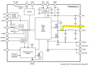
1. could you please help review the SCH? Vin=5V, Vout =0.95V/20A and 1V/26A.

2. section 7.3.1 tells the min requirements for Cin and Cout value as well as ESR requirement for polymer caps.

For Ceramic caps, should we consider DC bias effect?  Are the Cin=4x22u and Cout =4x47uF Nominal value or Effective Value?  Same question when determining RC compensation by table1

3. Is it necessary to place a SMT test point on COPM pin (pin 9)? and why?

4. what can we do on designing if we want to observe Switching node waveform on oscilloscope?

5. our EN pin is contorlled by MCU, but would met the situation that EN pin is floated. Is there internal pull-down on this pins? or should we place an external resistor?

Thanks very much!

  • Hello,

    Caleb is out for today, he will reply to this on Monday.

    Best,

    Calan

  • Hello BX27, 

    • I am filling up for Caleb, The input capacitor and input capacitors look good from what I can see n the attached SCH, But very hard to read the values of the other component to review. can you please attach a PDF or better resolution so we can the component value better? Always good practice to have high frequency capacitor, 0.1uF on the input and connect it as close as possible to the pin. 
    • the NC pins looks like they are not connected to PGND or AGND, please do so. These pins are internally isolated from any signal and all other pins. Each pinv must be soldered to a pad on the PCB. 
    • there is a not on the AGND that say optional, not sure what that means,
    • a 10K on PGOOD is good enough 
    • The caps mentioned in the datasheet are nominal value. or what we call capacitors as mentioned. Just make sure the derating on that capacitors used do not go below 80%  . typically look for temps and voltage deration that will maintain their values 
    • You can use PH pin to probe the internal SW node, it is connected internally. You can use a small VIA in your design for testing proposes only. Avoind long traces on this one as it is noisy node,   

    • COMP is the output of the error amplifier. No need to do the SMT connect unless you need it.
    • The EN pin requires a pull up to be enabled and requires to Pull this pin to AGND to disable the device

    Thanks!

    Tahar

  • HI Tahar, thanks for helping. 

    1. two SCH pdf is attached on the first post.

    2. NC pins will be solderd to pad on our pcb. Datasheet mentions they can be floated, so we assigned no electrical net to them.  since thet  internally isolated, what is the purpose of connecting them to AGND (we can do so)?

    3. "optional" 0 ohm connects  AGND and PGND as a single-point connection

    4. what if we use 100K rather than 10K on PGOOD ?

     5. So, The EN pin does not have internal pull-down resistor inside the IC, right?

    what is the device status if the input EN is Un-connected(floated) by mistake?

    Thanks!

  • Hello,

    1. I don't see two schematics attached on the first post. Only screenshots from the datasheet.

    2. Yes solder the to the pad on the PCB. It does not need to be connected to AGND per the datasheet.

    3. That is fine. It should be connected somewhere. If not through that specific 0ohm resistor, then somewhere else.

    4. 100kOhms on PGOOD would cause a slower rise on the PGOOD signal. We recommend staying around 10kOhms.

    5. The Enable pin does not have an internal pulldown resistor. If it is floating, voltage will slowly fall and the device will turn off after an unpredictable amount of time. This is why we ask you to ground the pin.

    Thanks,
    Caleb

  • Hi, Caleb,

    I deleted the attachments since nobody reply for a long time. I re-attach them in this reply. could you pls help review?

    Thanks !

    [deleted]

  • Hello,

    Thanks for reattaching. Looking at your schematics they look fine. Please follow the layout guidelines on the datasheet.

    Thanks,
    Caleb