This thread has been locked.

If you have a related question, please click the "Ask a related question" button in the top right corner. The newly created question will be automatically linked to this question.

UC2842A: Schematic Review Reguest

Part Number: UC2842A
Other Parts Discussed in Thread: UC2842

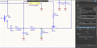
Hello, I've designed a flyback converter with UC2842 IC. Design is based on TI's tool and reference schematics and there is a problem, The AC Board's fuse keeps burning up. When I disable the fuse, R2-R5 resistors heat up a lot. When I disable them, the R15 resistor blows up.

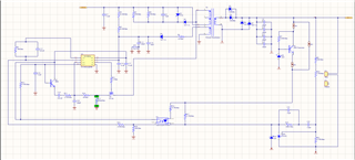
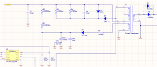
Transformer number: 750343068

 https://www.digikey.com/en/products/detail/w%C3%BCrth-elektronik/750343068/8594599

Optocoupler : FOD817ASD

https://www.digikey.com/en/products/detail/onsemi/FOD817ASD/1050252

  • Hi Tugba,

    Looks like you are facing an overcurrent issue at the primary side. If your fuse blows up, it means that more than 1A of current (according to schematic) is running at the primary side. If R2 and R5 are getting hot, it means that they are burning a lot of power, may be more or close than they are rated for. Similar for R15. Would you please share your design specifications?

    How much power is your flyback delivering? Input voltage? Output voltage? Switching frequency?

    Thank you.

  • Input voltage is universal AC voltage. Output specifications are : 24V DC 2A under load

    The switching frequency is 100kHz.

    If you'd like I can send you the full schematic in private. 

  • Hi Tugba, 

    I am taking care of this thread, and I will be back to you soon today. The full schematic is useful, you can send it privately to me. 

  • Hi Tugba,

    I just got the schematic and I will be back to you soon

  • Hi Tugba,

    1. If your Flyback is working in CCM (Continuous Conduction Mode):

    D=0.437 and L=1.16mH

    Your inductance value is 230uH. It is way too short. If that is the case, the ripple of the inductor and primary current will be too large and it can saturate your transformer. I recommend redesigning the inductor.

    2. What is the power rating of R2 and R5? Doing some calculations, at high voltage line, the power rating of the start-up resistors is P=(Vin-Vcc)^2/80kohms=1.7W. It means that each resistor should be rated for at least 0.85W (half each)I recommend using 3 resistors in series or increase the power rating or size.

    3. About your fuse, I recommend limiting the current limit of your power supply. It might that the fuse is very sensitive, and it blows up when the input current reaches a high peak when starting up the converter.

    Thank you.

  • Hi,

    Its not in CCM, I designed for DCM operation.

    You were right, power rating of R2 and also R5 is 1/4W. 

    The power supply I have only goes up to 120V, so I had to test my circuit by mains.

    Thank you! 

  • Hi Tugba,

    -For DCM, the inductance value is in good range. You can verify it using the power equation in the primary magnetizing inductance. 

    1/2*Ipp_max^2*Lp*fsw*n_xfrm=(Vout+Vf)*Iout at full power. Ipp_max is the max primary peak current. You can calculate Ippmax calculating D=sqrt(2*fs*Lp/Rload)*Vout/Vin.  n_xfmr is the efficiency of the transformer. Vf is forward voltage of diode. 

    -You can limit your source current in your power supply, both DC or mains to avoid burning your fuse, as it might be very sensitive.

    Thanks